Home - Coordinator
Jump to navigation
Jump to search


|

|

|
General Information
- The Coordinator is the device that receives information from the devices on the plant floor.
- The Coordinator communicates all information from the hardware devices to the VersaCall Software.
- This device communicates with hardware devices over a 900MHz band. VersaCall refers to this as our Mesh Network.
- Coordinators can be connected to the Computer/Server via USB port or over an Ethernet connection.
Specifications
- USB Connected
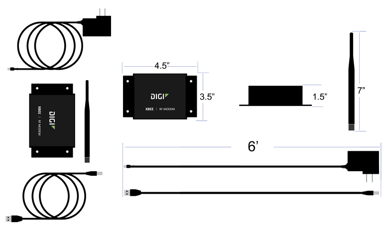
- Requirements
- 110v power outlet within 6 feet of placement/location.
- Control Unit within 6 feet of placement/location.
- Mounting location free of Metal Enclosures.
- Specifications
- Dimensions – 3.5” (W) x 4.5” (L) x 1.5” (H)
- (1) 6’ Power Cord (included)
- (1) 6’ USB Cord (included)
- (1) 7” Antenna (included)
- Remote - RS-232 Connected
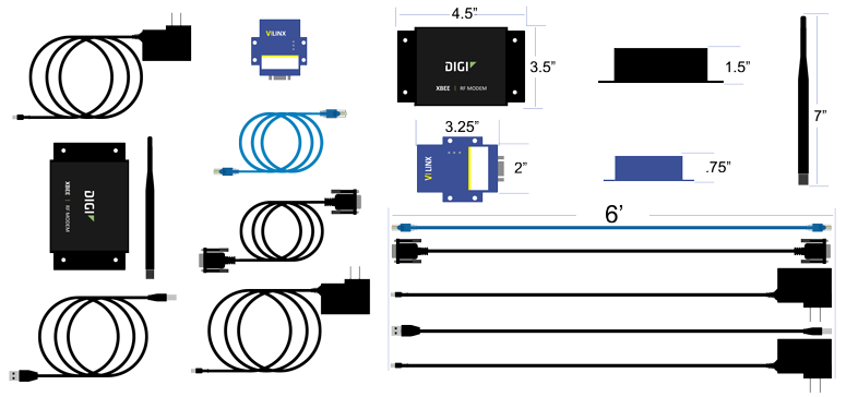
- Requirements
- (2) 110v power outlets within 6 feet of placement/location (Coordinator & RS-232).
- Coordinator & RS-232 within 6 feet of each other.
- Mounting location free of Metal Enclosures.
- Ethernet port near the placement/location of the RS-232.
- RS-232 will need to be assigned a Static IP Address or a DHCP Reserved address.
- Specifications
- Coordinator Dimensions – 3.5” (W) x 4.5” (L) x 1.5” (H)
- RS-232 Dimensions - s" (W) x 3.25" (L) x .75" (H)
- (2) 6’ Power Cords (included)
- (1) 6’ Serial Cable (included)
- (1) 7” Antenna (included)
- (1) Ethernet Cable (not included)
- Real-Port Connected
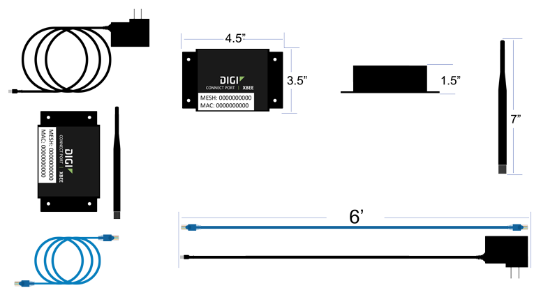
- Requirements
- 110v power outlet within 6 feet of placement/location.
- Mounting location free of Metal Enclosures.
- Ethernet port near the placement/location of the RS-232.
- Pre-Installed Static IP Address (VersaCall) or DHCP Reserved IP Address based on the MAC Address of the Coordinator (Customer IT).
- Specifications
- Dimensions – 3.5” (W) x 4.5” (L) x 1.5” (H)
- (1) 6’ Power Cord (included)
- (1) 6’ Ethernet Cord (included)
- (1) 7” Antenna (included)
Install Guides
- Instructions on Installing a USB type Coordinator
- Instructions on Installing an Ethernet/Remote Coordinator where the Coordinator & Computer/Server are on the Same Subnet
- Instructions on Installing an Ethernet/Remote Coordinator where the Coordinator & Computer/Server are on Different Subnets
- Instructions on Installing an Ethernet Connect Port X2 (Real-Port) Coordinator where the Coordinator & Computer/Server are on the Same Subnet
- Instructions on Installing an Ethernet Connect Port X2 (Real-Port) Coordinator where the Coordinator & Computer/Server are on Different Subnets
Step by Step Guides
Keyword Search
| Type Subject or Key Word to Query Archives |
|---|

|