VT3000 System Settings
Jump to navigation
Jump to search


|

|

|
General Information
- This section of the software allows the user to change Global Admin Settings, Service Settings and Web Interface Settings.
Global Settings
- Use this section to access the System Name, License, Debug Mode, Database Locations and Email Settings.
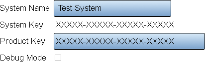
- General Information/Settings
- System Name - enter a name for the VT3000 system.
- System Key - this key is generated when the software is installed.
- Product Key - this is provided by VersaCall - contact support if this field is blank.
- Debug Mode - select this when instructed by a VersaCall Technician - this feature should not be selected by default.
- Database Location
- There are 3 database detail options - Administration, Configuration and Events. Use the arrow expansion icons to view all details for each database.
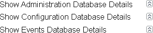
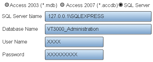
- Database Details
- Database Type - currently the only option available for selection is SQL Server.
- SQL Server Name - enter the name of the SQL Server where the databases are being stored. By default, the address will read 127.0.0.1\SQLEXPRESS.
- Database Name - by default the database names will be VT3000_Administration, VT3000_Configuration and VT3000_Events.
- User Name - enter the username for the account setup on SQL Server.
- Password - enter the password assigned to the username.
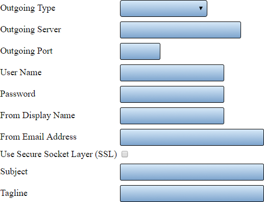
- Email Settings
- There are 3 types available - Disabled, Anonymous SMTP and Authenticated SMTP. Each selection will have the same fields shown but certain fields will not be available on Disabled and Anonymous SMTP.
- Outgoing Type - select Disabled, Anonymous SMTP or Authenticated SMTP.
- Outgoing Server - enter the name of the outgoing email server.
- Outgoing Port - enter the outgoing email server port.
- User Name - when using authenticated SMTP - enter the user name of the email account.
- Password - when using authenticated SMTP - enter the password for the email account.
- From Display Name - enter the name to be shown when using text messages.
- From Email Address - enter the email address to be shown when using email.
- Use Secure Socked Layer (SSL) - if your system requires SSL select this option.
- Subject - enter what will show on the subject line.
- Tagline - enter what will show at the bottom of all texts and emails. By default, this is set to date and time.
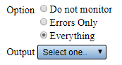
- System Monitoring
- This section is used to setup the monitoring of devices communicating with the system. You can monitor for errors or when communications have stopped.
- Option - Do Not Monitor - select this option if you do not want to monitor your devices.
- Option - Errors Only - select this option to monitor devices for SD Card Errors, Low Battery or Communications Not Received.
- Option - Everything - select this option to monitor for Errors & if the device has stopped communicating with the coordinator.
- Output - select the Output or Group that you want to send a communication to when there is an issue.
Service Settings
- The Service Settings page has 4 tabs available. Each tab will allow the user to edit a specific function in the software.
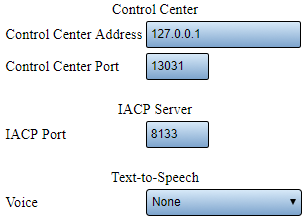
- General - Control Center
- Do Not alter any of the Control Center Settings unless instructed to by a VersaCall Technician.
- Control Center Address - the control center is software the communicates with all VersaCall software components - this is the server location.
- Control Center Port - this is the port that the control center uses to communicate.
- IACP Port - this is a specific port designated by the software - do not alter.
- Text-to-Speech - when using a phone modem or 2 way radio to communicate without audio files, select the Windows voice to be used when reading the communication messages.
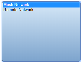
- Coordinator
- Use this tab to add or edit coordinators.
- List will show all Coordinators installed on the system.
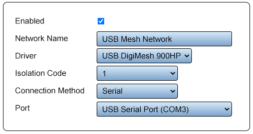
- Selecting a USB Coordinator from the list will open a Properties interface similar to the image below.
- Selecting a Remote (RS-232) Coordinator from the list will open a Properties interface similar to the image below.
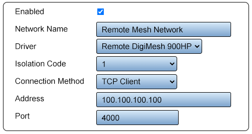
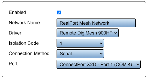
- Selecting a Remote X2 - RealPort Coordinator from the list will open a Properties interface similar to the image below.
- Paging Transmitter
- Use this tab to add or edit paging transmitters.
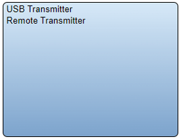
- List will show all Paging Transmitters installed on the system.
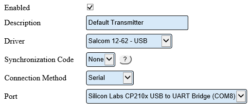
- Selecting a USB 12-62 Paging Transmitter from the list will open a Properties interface similar to the image below.
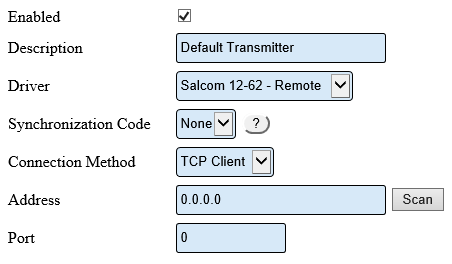
- Selecting a Remote 12-62 Paging Transmitter from the list will open a Properties interface similar to the image below.
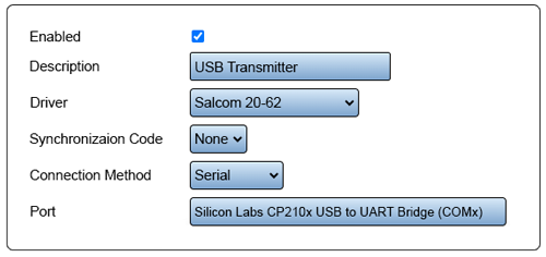
- Selecting a USB 20-62 Paging Transmitter from the list will open a Properties interface similar to the image below.
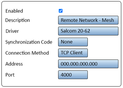
- Selecting a Remote 20-62 Paging Transmitter from the list will open a Properties interface similar to the image below.
- Audio Out
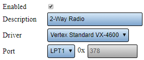
- Use this tab to add or edit phone modems and/or 2-way radios.
- Image below shows a 2-Way Radio Setup.
Keyword Search
| Type Subject or Key Word to Query Archives |
|---|

|