Difference between revisions of "VT3000 - Install Coordinator - Remote - Different Subnet"
SupportAdmin (talk | contribs) m (SupportAdmin moved page Installing a Remote Coordinator - Different Subnet to VT3000 - Install Coordinator - Remote - Different Subnet without leaving a redirect) |
SupportAdmin (talk | contribs) |
||
| Line 1: | Line 1: | ||
=Overview= | |||
This guide will show how to configure a remote coordinator that is on a different subnet than the VersaCall computer/server. For this method, you must have the IP address of the port that the RS232 device is plugged into – consult your IT department for this information. They may need to trace the device using the MAC address, this is printed on a label attached to the bottom of the RS-232 device. You will also need an IP address that you can use as a Static IP address for this device. | This guide will show how to configure a remote coordinator that is on a different subnet than the VersaCall computer/server. For this method, you must have the IP address of the port that the RS232 device is plugged into – consult your IT department for this information. They may need to trace the device using the MAC address, this is printed on a label attached to the bottom of the RS-232 device. You will also need an IP address that you can use as a Static IP address for this device. | ||
===Instructions=== | |||
---- | |||
'''1.''' First connect the RS232-Over-Ethernet device (VESP211-232) by plugging it in to the Ethernet port setup by IT and connecting the power. Attach the serial cable to the Coordinator and the RS232 device. Connect the power plug to the coordinator then connect it to power. | '''1.''' First connect the RS232-Over-Ethernet device (VESP211-232) by plugging it in to the Ethernet port setup by IT and connecting the power. Attach the serial cable to the Coordinator and the RS232 device. Connect the power plug to the coordinator then connect it to power. | ||
Revision as of 16:01, 17 August 2017
Overview
This guide will show how to configure a remote coordinator that is on a different subnet than the VersaCall computer/server. For this method, you must have the IP address of the port that the RS232 device is plugged into – consult your IT department for this information. They may need to trace the device using the MAC address, this is printed on a label attached to the bottom of the RS-232 device. You will also need an IP address that you can use as a Static IP address for this device.
Instructions
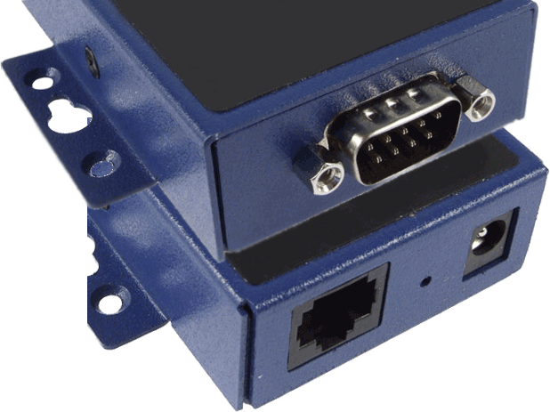
1. First connect the RS232-Over-Ethernet device (VESP211-232) by plugging it in to the Ethernet port setup by IT and connecting the power. Attach the serial cable to the Coordinator and the RS232 device. Connect the power plug to the coordinator then connect it to power.
2. Open a web browser (IE, Firefox or Chrome) – in a new tab type in the IP address for the port the RS232 device in plugged into or the IP address that was obtained by tracing the MAC address.
3. A login page will show – leave the Password field blank – click on the Login button.
4. The first option will be to enter a name for the device – enter any name that will help you identify it in the future – click on the Next button.
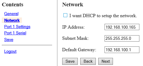
5. The next option allows you to setup a static IP address for the RS232 device. Enter in the information provided by your IT department – click on the Next button.
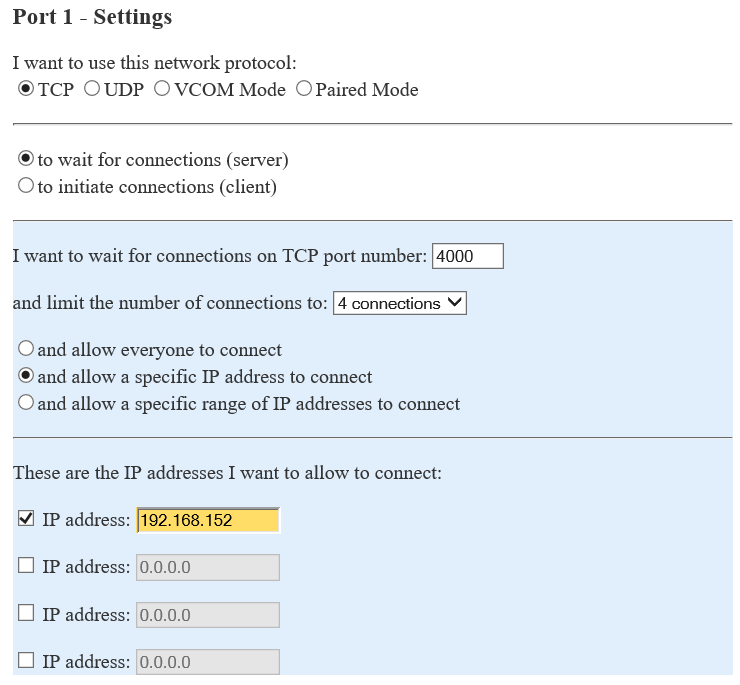
6. The next option is for setting up the type of Port connection that will be used.
    a. Network Protocol – select TCP – select “to wait for connections”.
    b. Port Number – enter 4000 for the Port number unless told otherwise by IT.
    c. Limit – select 4 connections from the drop down list.
    d. IP Address – enter the IP address of the VersaCall computer. If you do not know the IP address, please contact IT for further assistance.
NOTE: The IP address shown in the image is just for reference purposes – only use the IP address of your VersaCall computer.
Click on the Advanced button when all settings have been entered.
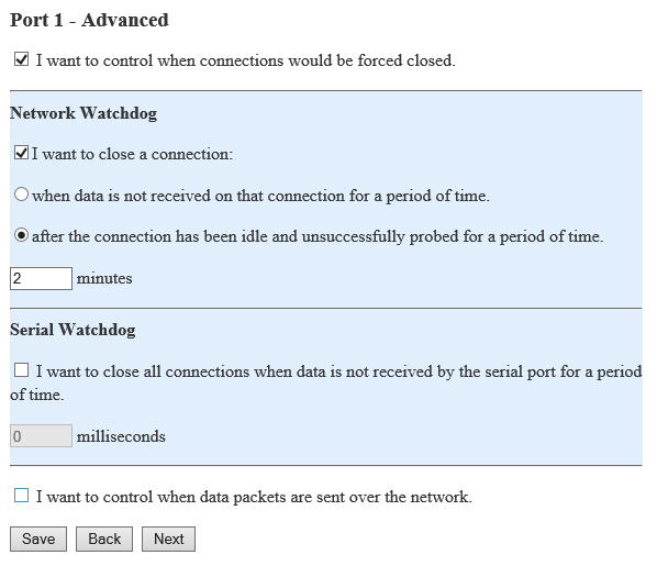
7. The Advanced Port settings page will load.
    a.	Advanced – click in the box next to “I want to control when connections would be forced to close” to place a check mark in it.
    b.	Network – click in the box next to “I want to close a connection” to place a check mark in it.
            i.	Select “after the connection ……” and enter 2 in the field for minutes.
    c.	Serial – uncheck the box and leave the milliseconds field blank.
    d.	Data Packets – do not select the option to control data packets.
Once all the settings have been entered click on the Next button.
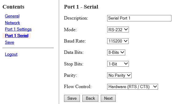
8. The Port 1 – Serial option will load:
    a.	Description – enter Serial Port 1
    b.	Mode – select RS-232
    c.	Baud Rate – select 115200
    d.	Data Bits – select 8-Bits
    e.	Stop Bits – select 1-Bit
    f.	Parity – select No Parity
    g.	Flow Control – select Hardware (RTS/CTS)
Once all fields have been addressed click on the Next button.
9. The final option is to Save the changes that have been made – click on the Save button.
10. The Device will reboot – close the webpage – open a new tab and go to the VT3000 home page – select VT3000 – select Administration – select System Settings – select Service.
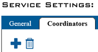
11. On the Service Settings page select the Coordinator tab – click on the add or “+” icon.
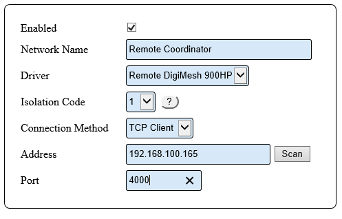
12. A settings window will show for the new coordinator.
    a.	Enabled – click on the box to place a check mark – this will enable the device.
    b.	Network Name – enter any name that you wish. This name will show on the Device Status page.
    c.	Driver – select the Remote DigiMesh 900HP driver from the list.
    d.	Isolation Code – if this is the only coordinator, leave the number as 1. If this is an additional coordinator select 2.
    e.	Connection Method – select TCP Client from the list.
    f.	Address – enter the IP address for the device (one entered in step 6).
    g.	Port – enter 4000.
13. Click on the Save & Exit button in the top right corner of the screen.
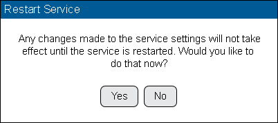
14. A screen will appear telling the user they need to restart the VersaCall service in order to commit the changes that were made – click on the Yes button. If this is not done, the system will not communicate with the device.
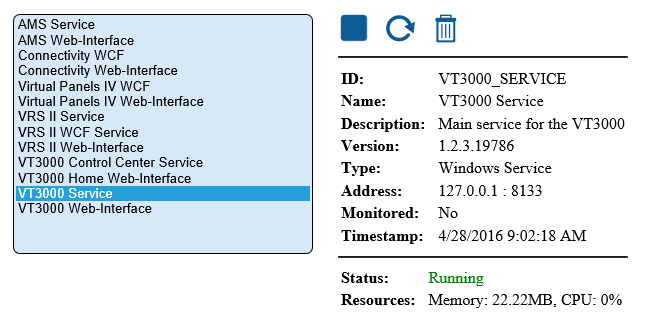
15. The Control Center page will load – the VT3000 Service will already be highlighted in the list – click on the Stop button (blue square icon).
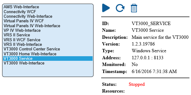
16. The page will refresh and show the Status as Stopped – the Stop button will be replaced by the Start button (blue triangle icon). Click on the Start button.
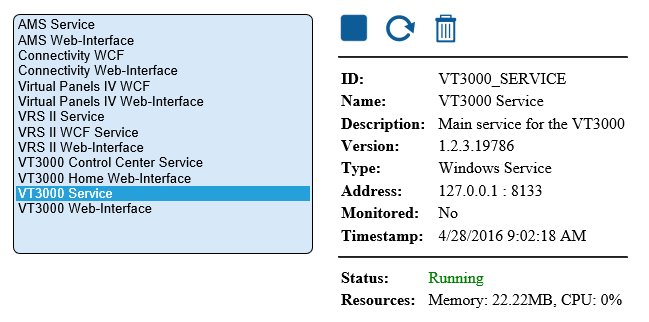
17. The page will refresh show the Status as Started along with the Stop button replacing the Start button.
18. Now you will need to check Device Status to ensure that the system is communicating with the device. From the Home screen select Diagnostics – Device Status.
19. The device status page will show the coordinator in red meaning it is not communicating with it. This is normal as it can take up to 30 seconds for the system to establish a connection with the device.
20. After 30 seconds to 1 minute the page will refresh and the coordinator will show in black. This indicates that a connection has been made with the device. Other modules will begin to show if they have been powered up.
This concludes the How To – if you are experiencing any difficulties or if the coordinator is not making a connection please contact VersaCall service.
