Difference between revisions of "VT3000 System Settings"
SupportAdmin (talk | contribs) |
SupportAdmin (talk | contribs) |
||
| Line 276: | Line 276: | ||
'''c. Drive''' - select Vertex Standard or Motorola XPR. | '''c. Drive''' - select Vertex Standard or Motorola XPR. | ||
'''d. Port''' - by default the port will be LPT1. | '''d. Port''' - by default the port will be LPT1. | ||
<br> | |||
---- | |||
---- | |||
= | <br> | ||
{|style="margin:auto;" | |||
[[ | |valign="top" | | ||
{|class="wikitable" style="text-align:center; background:#eaf3ff; width: 200px;" | |||
|- | |||
|[[Special:Categories|<big>'''Help by Category'''</big>]] | |||
[[ | |} | ||
|valign="top" | | |||
{|class="wikitable" style="text-align:center; background:#eaf3ff; width: 200px;" | |||
|- | |||
|[[VT3000_How To Guides|<big>'''Step by Step Guides'''</big>]] | |||
|} | |||
[[ | |valign="top" | | ||
{|class="wikitable" style="text-align:center; background:#eaf3ff; width: 200px;" | |||
|- | |||
|[[https://www.versacall.com/customer-support/service-ticket|<big>'''Submit a Ticket'''</big>]] | |||
[[ | |} | ||
|valign="top" | | |||
{|class="wikitable" style="text-align:center; background:#eaf3ff; width: 200px;" | |||
|- | |||
= | |[[https://www.versacall.com/training|<big>'''Training Videos'''</big>]] | ||
|} | |||
< | |} | ||
{|style="margin:auto;" | |||
</ | |valign="top" | | ||
{|class="wikitable" style="text-align:center; background:#eaf3ff; width: 800px;" | |||
|- | |||
|colspan="2"|<inputbox> | |||
type=search | |||
default=Search VersaCall Support | |||
</inputbox> | |||
|} | |||
|} | |||
Revision as of 22:48, 8 March 2022
Overview
This section of the software allows the user to change Global Admin Settings, Service Settings and Web Interface Settings.
Global Settings
Use this section to access the System Name, License, Debug Mode, Database Locations and Email Settings.
General Information/Settings
1. General Information/Settings Properties:
    a. System Name - enter a name for the VT3000 system.
    b. System Key - this key is generated when the software is installed.
    c. Product Key - this is provided by VersaCall - contact support if this field is blank.
    d. Debug Mode - select this when instructed by a VersaCall Technician - this feature should not be selected by default.
Database Locations
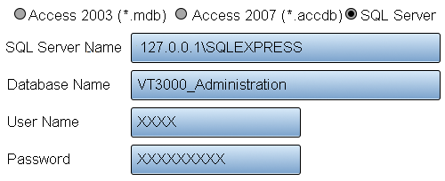
There are 3 database detail options - Administration, Configuration and Events. Select the arrow icon to expand the details.
1. Database Locations Properties:
    a. Database Type - currently the only option available for selection is SQL Server.
    b. SQL Server Name - enter the name of the SQL Server where the databases are being stored. By default, the address will read 127.0.0.1\SQLEXPRESS.
    c. Database Name - by default the database names will be VT3000_Administration, VT3000_Configuration and VT3000_Events.
    d. User Name - enter the username for the account setup on SQL Server.
    e. Password - enter the password assigned to the username.
Email Settings
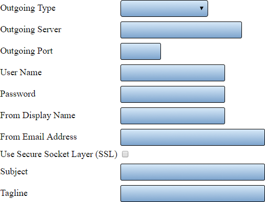
There are 3 types available - Disabled, Anonymous SMTP and Authenticated SMTP. Each selection will have the same fields shown but certain fields will not be available on Disabled and Anonymous SMTP.
1. Email Settings Properties:
    a. Outgoing Type - select Disabled, Anonymous SMTP or Authenticated SMTP.
    b. Outgoing Server - enter the name of the outgoing email server.
    c. Outgoing Port - enter the outgoing email server port.
    d. User Name - when using authenticated SMTP - enter the user name of the email account.
    e. Password - when using authenticated SMTP - enter the password for the email account.
    f. From Display Name - enter the name to be shown when using text messages.
    g. From Email Address - enter the email address to be shown when using email.
    h. Use Secure Socked Layer (SSL) - if your system requires SSL select this option.
    i. Subject - enter what will show on the subject line.
    j. Tagline - enter what will show at the bottom of all texts and emails. By default, this is set to date and time.
System Monitoring
This section is used to setup the monitoring of devices communicating with the system. You can monitor for errors or when communications have stopped.
1. System Monitoring Properties:
    a. Option - 3 options are available.
         i. Do Not Monitor - select this option if you do not want to monitor your devices.
         ii. Errors Only - select this option to monitor devices for SD Card Errors, Low Battery or Communications Not Received.
         iii. Everything - select this option to monitor for Errors & if the device has stopped communicating with the coordinator.
    b. Output - select the Output or Group that you want to send a communication to when there is an issue.
Service Settings
The Service Settings page has 4 tabs available. Each tab will allow the user to edit a specific function in the software.
General
Do not alter any of the settings shown in this section unless instructed by a VersaCall Technician.
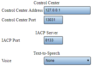
1. Control Center Properties:
    a. Control Center Address - the control center is software the communicates with all VersaCall software components - this is the server location.
    b. Control Center Port - this is the port that the control center uses to communicate.
    c. IACP Port - this is a specific port designated by the software - do not alter.
    d. Text-to-Speech - when using a phone modem or 2 way radio to communicate without audio files, select the Windows voice to be used when reading the communication messages.
Coordinator
Use this tab to add or edit attached coordinators. Click on one of the links (under Step by Step Guides section) for specific instructions on installing a coordinator.
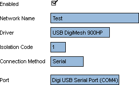
1. USB Coordinator Properties:
    a. Enabled – place a check mark in the box to enable the device.
    b. Network Name – enter a name for the coordinator.
    c. Driver – select USB Digi Mesh 900HP.
    d. Isolation Code – leave this set to 1 unless VersaCall instructs you to change it.
    e. Port – select the COM port labeled as Digi USB Serial Port.
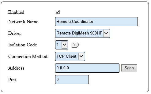
2. Remote Coordinator Properties:
    a. Enabled – click on the box to place a check mark – this will enable the device.
    b. Network Name – enter any name that you wish. This name will show on the Device Status page.
    c. Driver – select the Remote Digi Mesh 900HP driver from the list.
    d. Isolation Code – leave the number as 1 unless installing an additonal coordinator.
    e. Connection Method – select TCP Client from the list.
    f. Address – click on the Scan button.
Paging Transmitter
Use this tab to add or edit attached paging transmitters. Click on one of the links (under Step by Step Guides section) for specific instructions on installing a paging transmitter.
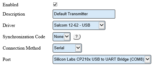
1. USB Paging Transmitter Properties:
    a. Enabled – place a check mark in the box to enable.
    b. Description – enter a name for the transmitter.
    c. Driver – select Salcom 12-62 – USB.
    d. Synchronization Code – leave this set to None unless told to change by a VersaCall Technician.
    e. Connection Method – leave this set to Serial.
    f. Port – click on the down arrow and select the “Silicon Labs CP210x USB to UART Bridge” port.
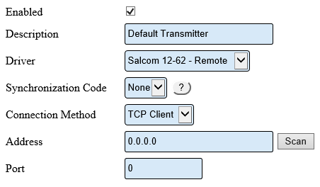
2. Remote Paging Transmitter Properties:
    a. Enabled – click on the box to place a check mark – this will enable the device.
    b. Description – enter any name for the transmitter.
    c. Driver – select the Salcom 12-62 - Remote driver from the list.
    d. Synchronization Code – if this is your only paging transmitter, leave the field as None. Use different codes for multiple transmitters.
    e. Connection Method – select TCP Client from the list.
    f. Address – click on the Scan button.
Audio Out
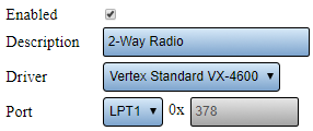
This is most commonly used to setup a 2-Way Radio. Below is an example of the most common setup.
1. Audio Out Properties:
    a. Enabled - select if the output is to be used.
    b. Description - enter a name for the output device.
    c. Drive - select Vertex Standard or Motorola XPR.
    d. Port - by default the port will be LPT1.
|
|
|
|
|
| ||


