Difference between revisions of "VT3000 - Install Rack Mount PC"
Jump to navigation
Jump to search
SupportAdmin (talk | contribs) |
SupportAdmin (talk | contribs) m (Text replacement - "https://www.linkedin.com/company/versacall-technologies-inc-/mycompany/" to "https://www.linkedin.com/company/versacall/") |
||
| (7 intermediate revisions by the same user not shown) | |||
| Line 1: | Line 1: | ||
{|style="margin:left;" | {|style="background:transparent; color:black" border="0" height="230" align="center" valign="bottom" | ||
|+style="background:transparent| | |||
|-align="center" | |||
| | |||
|[[Image:CallUsBtn.png|Call Now 858-677-6766]] | |||
| | |||
|[[Image:SubmitTckBtn.png|link=https://www.versacall.com/customer-support/service-ticket]] | |||
| | |||
|[[Image:EmailUsBtn.png|link=mailto:[email protected]?Subject=Help%20Needed%20Wiki&body=Type%20Message%20Here]] | |||
|} | |||
<br> | |||
---- | |||
---- | |||
<br> | |||
[[File:GeneralHeader.png]] | |||
<br> | |||
{|style="margin:left; width: 100px; background:#eaf3ff; padding:5px; border:2px solid #000000;" | |||
|- | |||
|<big>'''Overview'''</big> | |||
{|style="margin:left; width: 800px; background:#F0F0F0; padding:5px; border:2px solid #000000;" | |||
|valign="top" | | |valign="top" | | ||
|- | |- | ||
|All New Systems come with a computer or control unit that contains the VersaCall software. If your company provided the PC or Server then you will need to speak with your IT department to determine where that hardware is located/installed. The instructions below are for a Server Control Unit, if this is the type of Control Unit you have purchased please proceed with the steps below. | |All New Systems come with a computer or control unit that contains the VersaCall software. If your company provided the PC or Server then you will need to speak with your IT department to determine where that hardware is located/installed. The instructions below are for a Server Control Unit, if this is the type of Control Unit you have purchased please proceed with the steps below. | ||
|} | |} | ||
|} | |} | ||
{|style="margin:left;" | <br> | ||
{|style="margin:left; width: 100px; background:#eaf3ff; padding:5px; border:2px solid #000000;" | |||
|- | |||
|<big>'''Requirements'''</big> | |||
{|style="margin:left; width: 800px; background:#F0F0F0; padding:5px; border:2px solid #000000;" | |||
|valign="top" | | |valign="top" | | ||
{|class="wikitable" style=" | {| class="wikitable mw-collapsible mw-collapsed" width="775px;" | ||
|- | |||
|style="text-align: center;" | '''See Requirements Here''' | |||
|- | |||
|'''1.''' VersaCall provided Server with software installed. | |||
|- | |- | ||
|'''2.''' Open rack mounting position. | |||
|- | |- | ||
| | |'''3.''' Power Outlet within 6 feet of the rack mounting position. | ||
|- | |- | ||
| | |'''4.''' If you are connecting to your network, ethernet cable and available port near the rack mounting position. | ||
|} | |||
|} | |} | ||
|} | |} | ||
<br> | |||
{|style="margin:left; width: 100px; background:#eaf3ff; padding:5px; border:2px solid #000000;" | |||
< | |||
{| | |||
|- | |- | ||
| < | |<big>'''Hardware Components'''</big> | ||
{|style="margin:left; width: 800px; background:#F0F0F0; padding:5px; border:2px solid #000000;" | |||
|valign="top" | | |||
|- | |||
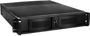
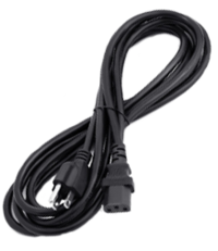
|[[File:ser5.png|center|300px|Server Unit]] || [[File:ser6.png|center|200px|Power Cord]] | |||
|} | |} | ||
|} | |||
<br> | |||
{| | ---- | ||
|<big>'''Step | ---- | ||
<br> | |||
[[File:InstructionHeader.png]] | |||
<br> | |||
{|style="margin:left; width: 100px; background:#eaf3ff; padding:5px; border:2px solid #000000;" | |||
|- | |||
|<big>'''Step 1.'''</big> | |||
{|style="margin:left; width: 800px; background:#F0F0F0; padding:5px; border:2px solid #000000;" | |||
|valign="top" | | |||
|- | |||
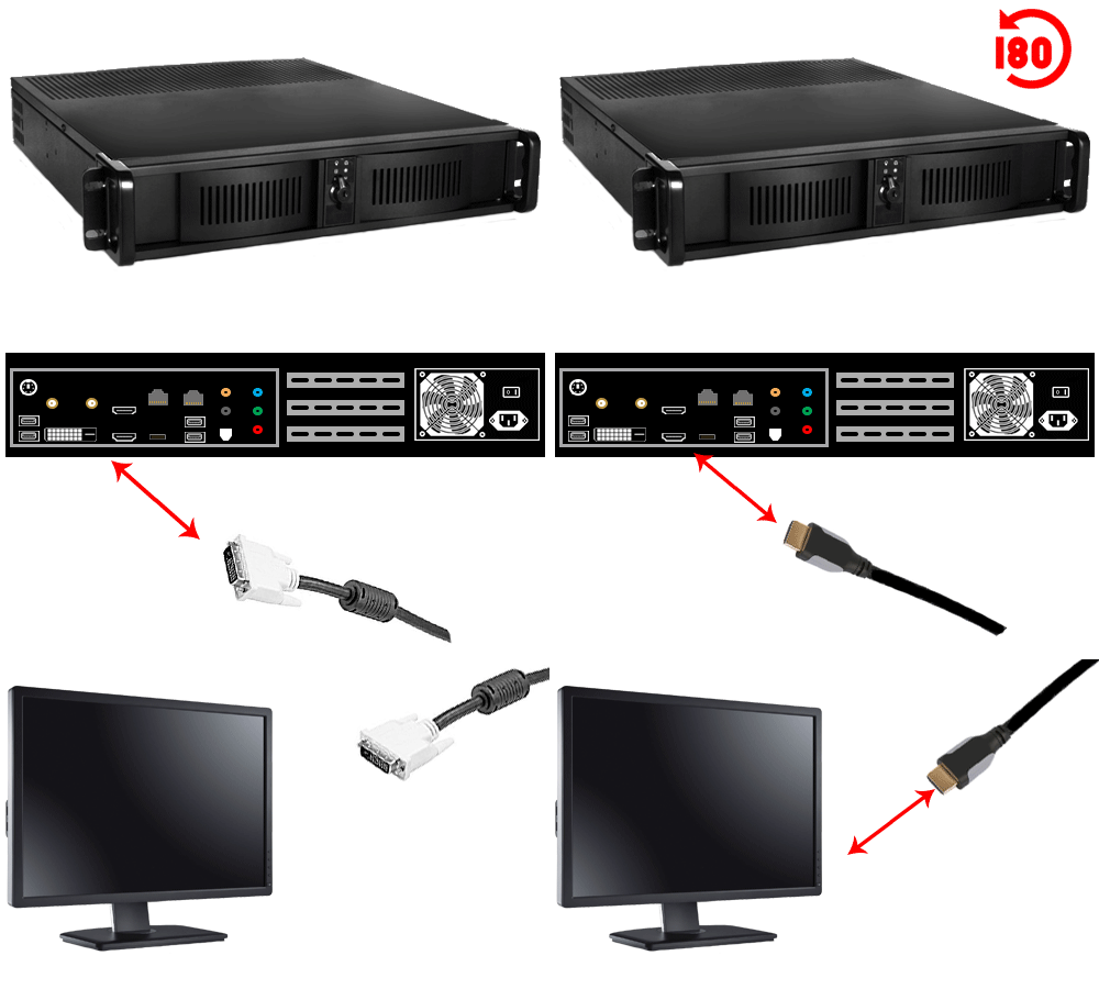
|Attach a Monitor (not included) to the Control Unit using the DVI or HDMI port. | |||
{|style="margin:left;" | |||
|valign="top" | | |||
{|class="wikitable" style=" align="center; " background:white;" | |||
|- | |- | ||
| | |[[File:Server1.gif]] | ||
|} | |||
|} | |||
|} | |} | ||
|} | |||
<br> | |||
---- | |||
<br> | |||
{|style="margin:left; width: 100px; background:#eaf3ff; padding:5px; border:2px solid #000000;" | |||
|- | |- | ||
| < | |<big>'''Step 2.'''</big> | ||
{|style="margin:left; width: 800px; background:#F0F0F0; padding:5px; border:2px solid #000000;" | |||
|valign="top" | | |||
|- | |||
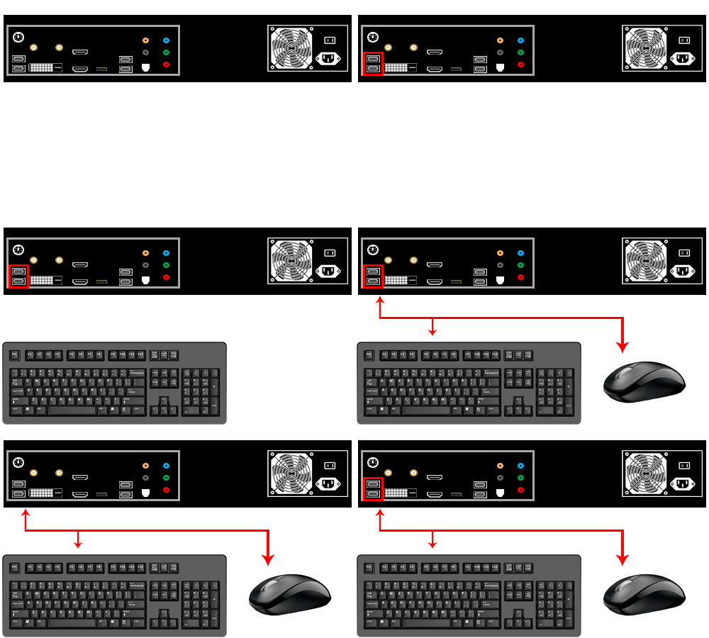
|Attach a Keyboard & Mouse (not included) to the Control Unit using the USB or PS/2 ports. | |||
{|style="margin:left;" | |||
|valign="top" | | |||
{|class="wikitable" style="background:white;" | |||
|- | |||
|[[File:Server2.gif]] | |||
|} | |||
|} | |||
|} | |||
|} | |||
<br> | |||
---- | |||
<br> | |||
{|style="margin:left; width: 100px; background:#eaf3ff; padding:5px; border:2px solid #000000;" | |||
|- | |||
|<big>'''Step 3.'''</big> | |||
{|style="margin:left; width: 800px; background:#F0F0F0; padding:5px; border:2px solid #000000;" | |||
|valign="top" | | |||
|- | |||
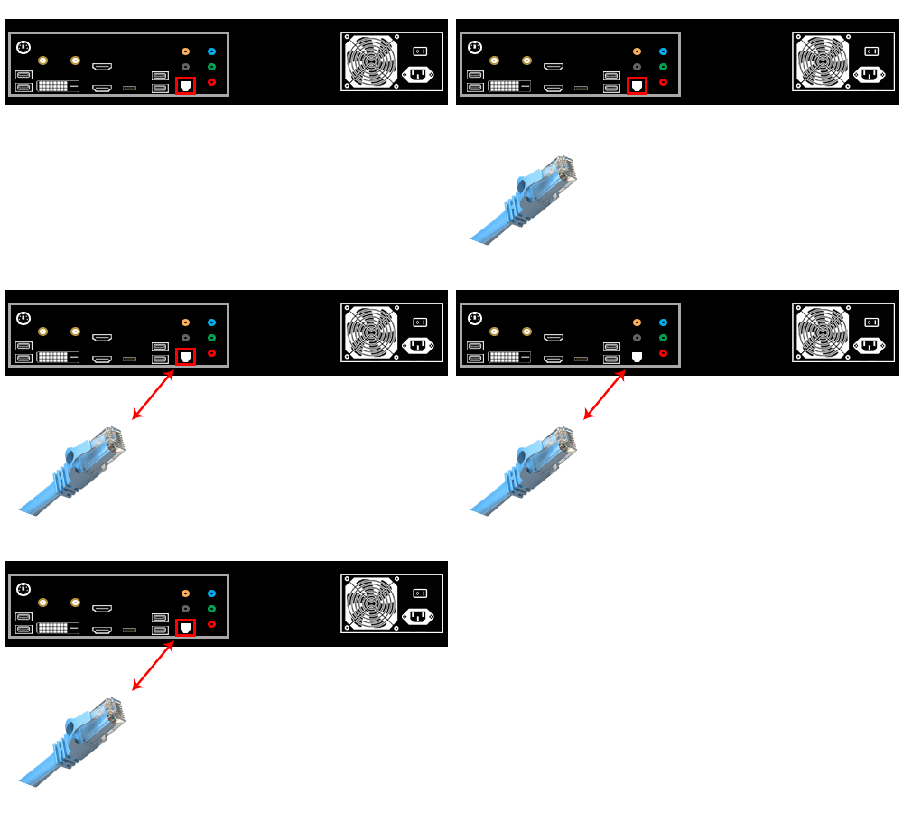
|If the unit is going on your network, attach an ethernet cable to the ethernet port. | |||
{|style="margin:left;" | |||
|valign="top" | | |||
{|class="wikitable" style="background:white;" | |||
|- | |||
|[[File:Server3.gif]] | |||
|} | |||
|} | |||
|} | |||
|} | |} | ||
<br> | |||
---- | |||
{| | <br> | ||
|<big>'''Step 4 | {|style="margin:left; width: 100px; background:#eaf3ff; padding:5px; border:2px solid #000000;" | ||
|- | |||
|<big>'''Step 4.'''</big> | |||
{|style="margin:left; width: 800px; background:#F0F0F0; padding:5px; border:2px solid #000000;" | |||
|valign="top" | | |||
|- | |||
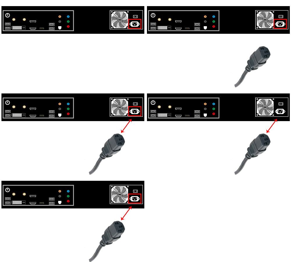
|Plug the Power Adapter into the power port. Connect the Power Adapter to Power Cord. | |||
{|style="margin:left;" | |||
|valign="top" | | |||
{|class="wikitable" style="background:white;" | |||
|- | |- | ||
| | |[[File:Server4.gif]] | ||
|} | |||
|} | |||
|} | |} | ||
|} | |||
<br> | |||
---- | |||
<br> | |||
{|style="margin:left; width: 100px; background:#eaf3ff; padding:5px; border:2px solid #000000;" | |||
|- | |- | ||
| < | |<big>'''Step 5.'''</big> | ||
{|style="margin:left; width: 800px; background:#F0F0F0; padding:5px; border:2px solid #000000;" | |||
|valign="top" | | |||
|- | |||
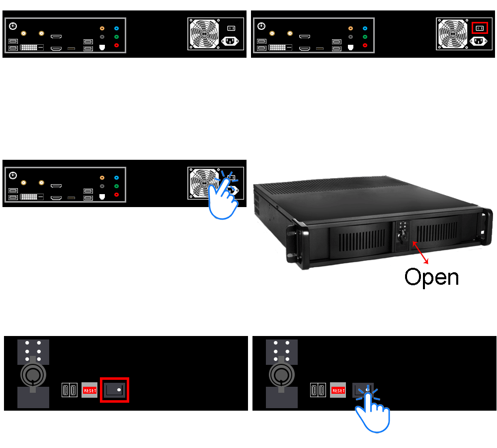
|Turn on the power in the back of the Server. Rotate to the front - open the protector door on the right. Press the Power Button (front). | |||
{|style="margin:left;" | |||
|valign="top" | | |||
{|class="wikitable" style="background:white;" | |||
|- | |||
|[[File:Server5.gif]] | |||
|} | |||
|} | |} | ||
|} | |||
|} | |||
{| | <br> | ||
|<big>'''Step 6 | ---- | ||
<br> | |||
{|style="margin:left; width: 100px; background:#eaf3ff; padding:5px; border:2px solid #000000;" | |||
|- | |||
|<big>'''Step 6.'''</big> | |||
{|style="margin:left; width: 800px; background:#F0F0F0; padding:5px; border:2px solid #000000;" | |||
|valign="top" | | |||
|- | |||
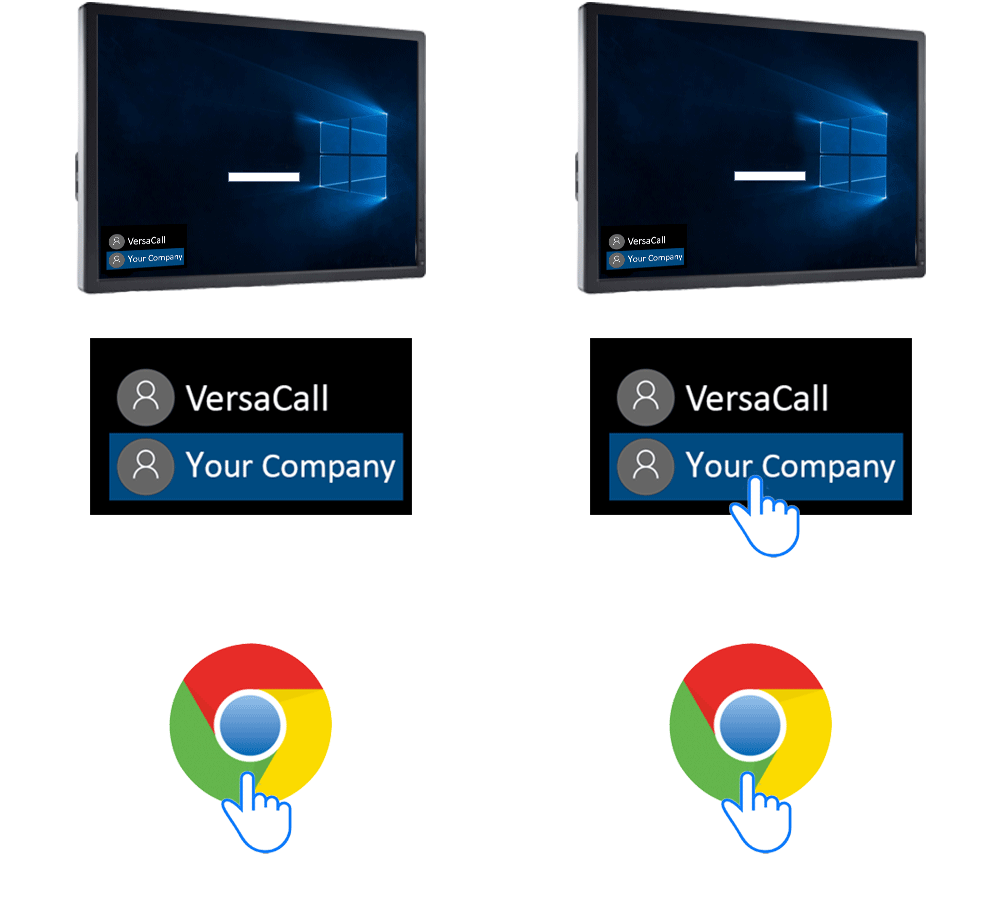
|After the computer boots - select "Your Company Name" as the user - select the Chrome icon from Windows Desktop. | |||
{|style="margin:left;" | |||
|valign="top" | | |||
{|class="wikitable" style="background:white;" | |||
|- | |- | ||
| | |[[File:InstallMini6.gif]] | ||
|} | |||
|} | |||
|} | |||
|} | |} | ||
<br> | |||
---- | |||
{| | <br> | ||
{|style="margin:left; width: 100px; background:#eaf3ff; padding:5px; border:2px solid #000000;" | |||
|- | |- | ||
| < | |<big>'''Step 7.'''</big> | ||
{|style="margin:left; width: 800px; background:#F0F0F0; padding:5px; border:2px solid #000000;" | |||
|valign="top" | | |||
|- | |||
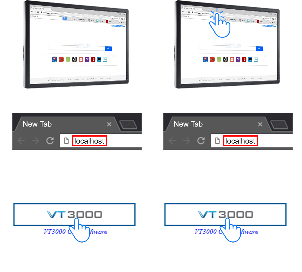
|Type "localhost" in the address bar - select VT3000 button on welcome page. | |||
{|style="margin:left;" | |||
|valign="top" | | |||
{|class="wikitable" style="background:white;" | |||
|- | |||
|[[File:InstallMini7.gif]] | |||
|} | |||
|} | |||
|} | |||
|} | |} | ||
<br> | |||
---- | |||
{| | <br> | ||
|<big>'''Step 8 | {|style="margin:left; width: 100px; background:#eaf3ff; padding:5px; border:2px solid #000000;" | ||
|- | |||
|<big>'''Step 8.'''</big> | |||
{|style="margin:left; width: 800px; background:#F0F0F0; padding:5px; border:2px solid #000000;" | |||
|valign="top" | | |||
|- | |||
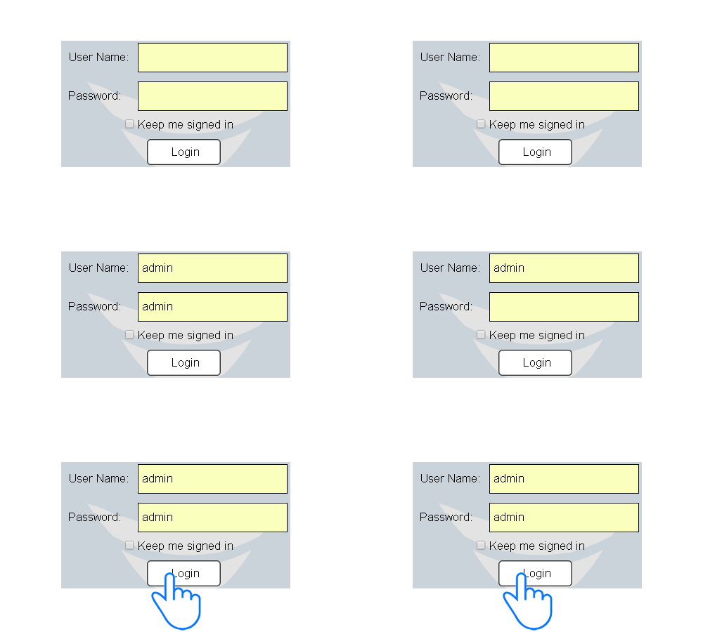
|Enter "admin" for User Name & Password - select Login button. | |||
{|style="margin:left;" | |||
|valign="top" | | |||
{|class="wikitable" style="background:white;" | |||
|- | |- | ||
| | |[[File:InstallMini8.gif]] | ||
|} | |||
|} | |||
|} | |||
|} | |} | ||
<br> | |||
---- | ---- | ||
---- | ---- | ||
<br> | |||
{|style="margin:auto;" | |||
{|style="margin: auto; | |+ | ||
| | [[File:RelatedHowTos.png|center]] | ||
{| class=" | |align="center" | | ||
{| class="wikitable mw-collapsible mw-collapsed" width="400px;" | |||
|- | |||
|style="text-align: center;" | '''Select a Guide Here''' | |||
|- | |- | ||
|[[VT3000 - IT Considerations|System Layout for IT Considerations/Information Purposes]] | |[[VT3000 - IT Considerations|System Layout for IT Considerations/Information Purposes]] | ||
| Line 97: | Line 231: | ||
|[[VT3000 - Install Standard PC|Installation Instructions for Standard PC Provided by VersaCall]] | |[[VT3000 - Install Standard PC|Installation Instructions for Standard PC Provided by VersaCall]] | ||
|} | |} | ||
| | |} | ||
<br> | |||
---- | |||
<br> | |||
{|style="margin:auto;" | |||
|+ | |||
[[File:SearchHeader.png|center]] | |||
|align="center" | | |||
{|class="wikitable" | |||
|- | |- | ||
| | |<inputbox>type=search</inputbox> | ||
|} | |||
| | |||
|} | |} | ||
| | <br> | ||
| | ---- | ||
<br> | |||
[[File:VC Footer.png|center]] | |||
{|style="background:transparent; color:black" border="0" height="200" align="center" valign="bottom" cellpadding=10px cellspacing=10px | |||
|+style="background:transparent| | |||
|-align="center" | |||
| | |||
|[[File:LinkedIn.png|Follow Us On LinkedIn|link=https://www.linkedin.com/company/versacall/]] | |||
| | |||
|[[File:BlogIcon.png|View our Blog|link=https://www.versacall.com/blog/]] | |||
|} | |} | ||
<br> | |||
[[Category:VT3000 Core Software]] | [[Category:VT3000 Core Software]] | ||
[[Category:System Hardware]] | [[Category:System Hardware]] | ||
[[Category:Control Unit - VersaCall Computer/Server]] | [[Category:Control Unit - VersaCall Computer/Server]] | ||
Latest revision as of 19:24, 20 April 2023

|

|

|
Overview
|
Requirements
|
| Hardware Components
|
Step 1.
|
Step 2.
|
Step 3.
|
Step 4.
|
Step 5.
|
Step 6.
|
Step 7.
|
Step 8.
|
|
|

|

