Difference between revisions of "VT3000 - IT Considerations"
SupportAdmin (talk | contribs) |
SupportAdmin (talk | contribs) |
||
| Line 17: | Line 17: | ||
{| role="presentation" class="wikitable mw-collapsible" | {| role="presentation" class="wikitable mw-collapsible" | ||
| <strong>Control Unit</strong> | | <strong>1. Control Unit</strong> | ||
|- | |- | ||
| Fundamentally, the VT3000 Control Unit is a Windows machine running the VT3000 software. There are multiple options for the control unit. | | Fundamentally, the VT3000 Control Unit is a Windows machine running the VT3000 software. There are multiple options for the control unit. | ||
| Line 26: | Line 26: | ||
<b>Virtual Control Unit</b> - There is the option to create a virtual Control Unit through VMWare or some other form of virtualization. This would all be provided by the customer. This virtual system should still exist on the same network as everything else, meaning that it is not recommended to utilize an “off-site” virtual server. It is important to note there are a couple of limitations with a virtual Control Unit such as: need to use remote versions of coordinators and paging transmitters, no phone support, no Two-Way Radio support. | <b>Virtual Control Unit</b> - There is the option to create a virtual Control Unit through VMWare or some other form of virtualization. This would all be provided by the customer. This virtual system should still exist on the same network as everything else, meaning that it is not recommended to utilize an “off-site” virtual server. It is important to note there are a couple of limitations with a virtual Control Unit such as: need to use remote versions of coordinators and paging transmitters, no phone support, no Two-Way Radio support. | ||
<b>Operating System</b> - the Control Unit is a Windows based system. There are a variety of operating systems that can be used. <b>NOTE:</b> A VersaCall provided Control Unit, only desktop/Professional versions of operating systems are available. Any server versions will need to be provided by the customer. | |||
Windows 7 Professional | Windows 7 Professional | ||
Windows 10 Professional | Windows 10 Professional | ||
| Line 40: | Line 34: | ||
Server 2014 | Server 2014 | ||
Server 2016 | Server 2016 | ||
<b>Minimum Requirements</b> - [[VT3000_-_Minimum_Requirements|'''Click Here''']] for Control Unit requirements - PC, Server & Virtual Server. | |||
<b>Static IP Address</b> - It is highly recommended that you provide the Control Unit with a static IP address (or at least a DHCP reserved one). This makes it more consistent when providing links to the system without the danger of the Control Unit’s IP address changing. | |||
<b>Webserver</b> - All the user interfaces for the VT3000 software are web based. This means that the VT3000 Control Unit needs to run Internet Information Services (IIS). | |||
<b>Software Dependencies</b> - The VT3000 software was is based on Microsoft.NET meaning that it needs the .NET Framework to operate. Any VT3000 system will need Microsoft.NET 4.6 or newer to run. | |||
<b>SLQ Server</b> - The VT3000 system stores its configuration and any captured events into SQL Server databases. There can be up to 8 databases used by the VT3000. Due to cost considerations, the VT3000 system software typically would use an Express version of SQL Server. SQL Server Express would be installed locally on the Control Unit. The VT3000 software supports SQL Server 2008 or newer. If you want, you can either install a full version of SQL Server on the Control Unit or else point the Control Unit at an existing SQL Server instance. If using an existing SQL Server instance, it is recommended that this instance exists on the local network and not at a different location (say the company headquarters). | |||
|} | |} | ||
| Line 87: | Line 49: | ||
{| role="presentation" class="wikitable mw-collapsible" | {| role="presentation" class="wikitable mw-collapsible" | ||
| <strong>Mesh Network</strong> | | <strong>2. Mesh Network</strong> | ||
|- | |- | ||
|The VT3000 system can utilize a variety of mesh devices: Call Stations, BSC Modules, Production Status Modules, Touch Input Modules, Wireless Switch Contact Modules, Wireless Lights, Wireless Audio Modules, etc. These devices all communicate on the mesh network. The mesh network is a proprietary technology (not to be confused with Wi-Fi or 802.11) that is loosely based on Zigbee (IEEE 802.15.4). It is a self-building mesh network meaning that as more devices are added to it, the coverage of that network is increased. It operates in the 920-928 MHz band. Indoors we typically can get about 400-500 feet per hop of coverage. A “hop” being the distance from one device to the next. A repeater can be utilized to increase coverage range. A repeater has a higher gain antenna and typically will be mounted in a better location than your typical devices allowing a better range of coverage. All a repeater requires is a standard power outlet. | |The VT3000 system can utilize a variety of mesh devices: Call Stations, BSC Modules, Production Status Modules, Touch Input Modules, Wireless Switch Contact Modules, Wireless Lights, Wireless Audio Modules, etc. These devices all communicate on the mesh network. The mesh network is a proprietary technology (not to be confused with Wi-Fi or 802.11) that is loosely based on Zigbee (IEEE 802.15.4). It is a self-building mesh network meaning that as more devices are added to it, the coverage of that network is increased. It operates in the 920-928 MHz band. Indoors we typically can get about 400-500 feet per hop of coverage. A “hop” being the distance from one device to the next. A repeater can be utilized to increase coverage range. A repeater has a higher gain antenna and typically will be mounted in a better location than your typical devices allowing a better range of coverage. All a repeater requires is a standard power outlet. | ||
| Line 95: | Line 57: | ||
{| role="presentation" class="wikitable mw-collapsible" | {| role="presentation" class="wikitable mw-collapsible" | ||
| <strong>Coordinators</strong> | | <strong>3. Coordinators</strong> | ||
|- | |- | ||
|For the system to communicate over the mesh network, it needs a Coordinator. A Coordinator is basically a 900 MHz radio. Typically, a Coordinator is a USB device that would be connected to the Control Unit. It also requires power through a standard power outlet. | |For the system to communicate over the mesh network, it needs a Coordinator. A Coordinator is basically a 900 MHz radio. Typically, a Coordinator is a USB device that would be connected to the Control Unit. It also requires power through a standard power outlet. | ||
| Line 103: | Line 65: | ||
{| role="presentation" class="wikitable mw-collapsible" | {| role="presentation" class="wikitable mw-collapsible" | ||
| <strong>Remote Coordinators</strong> | | <strong>4. Remote Coordinators</strong> | ||
|- | |- | ||
|There is the option to do what we refer to as a Remote Coordinator. This utilizes a Serial-Over-Ethernet device to allow us to position the coordinator anywhere we want and connect it to the Control Unit through a TCP connection over the network. Remote Coordinators require a static IP address (or at least DHCP reserved). Remote Coordinators allow us to add multiple Coordinators to a system, this could be used for example to cover a building a mile down the road. Some considerations need to be addressed when using multiple Coordinators on a single system. | |There is the option to do what we refer to as a Remote Coordinator. This utilizes a Serial-Over-Ethernet device to allow us to position the coordinator anywhere we want and connect it to the Control Unit through a TCP connection over the network. Remote Coordinators require a static IP address (or at least DHCP reserved). Remote Coordinators allow us to add multiple Coordinators to a system, this could be used for example to cover a building a mile down the road. Some considerations need to be addressed when using multiple Coordinators on a single system. | ||
| Line 111: | Line 73: | ||
{| role="presentation" class="wikitable mw-collapsible" | {| role="presentation" class="wikitable mw-collapsible" | ||
| <strong>Paging Transmitters</strong> | | <strong>5. Paging Transmitters</strong> | ||
|- | |- | ||
|Another add-on option for a VT3000 system is an on-site paging transmitter. This allows the system to send messages to pagers near the system. Typically, a Paging Transmitter is a USB device that would be connected to the Control Unit. It also requires power though as standard power outlet. | |Another add-on option for a VT3000 system is an on-site paging transmitter. This allows the system to send messages to pagers near the system. Typically, a Paging Transmitter is a USB device that would be connected to the Control Unit. It also requires power though as standard power outlet. | ||
| Line 119: | Line 81: | ||
{| role="presentation" class="wikitable mw-collapsible" | {| role="presentation" class="wikitable mw-collapsible" | ||
| <strong>Remote Paging Transmitter</strong> | | <strong>6. Remote Paging Transmitter</strong> | ||
|- | |- | ||
|Like a Remote Coordinator, it is possible to do the same thing with a paging transmitter. Position it anywhere and have the Control Unit talk to it through the network. Remote paging transmitters make it possible to add multiple paging transmitters to increase coverage on a large site. Some care needs to be taken in positioning these paging transmitters though. | |Like a Remote Coordinator, it is possible to do the same thing with a paging transmitter. Position it anywhere and have the Control Unit talk to it through the network. Remote paging transmitters make it possible to add multiple paging transmitters to increase coverage on a large site. Some care needs to be taken in positioning these paging transmitters though. | ||
| Line 127: | Line 89: | ||
{| role="presentation" class="wikitable mw-collapsible" | {| role="presentation" class="wikitable mw-collapsible" | ||
| <strong>Phone Communications</strong> | | <strong>7. Phone Communications</strong> | ||
|- | |- | ||
|An add-on module to the VT3000 system, allows it to communicate over a phone line. This makes the system capable of dialing a phone number or extension and synthesizing text to speech or playing a pre-recorded audio message. The most common use of this is to communicate through a PA system. This option requires that an analog phone line is provided. This option is not available on a Virtual Control Unit since the add-on module is a USB device. | |An add-on module to the VT3000 system, allows it to communicate over a phone line. This makes the system capable of dialing a phone number or extension and synthesizing text to speech or playing a pre-recorded audio message. The most common use of this is to communicate through a PA system. This option requires that an analog phone line is provided. This option is not available on a Virtual Control Unit since the add-on module is a USB device. | ||
| Line 135: | Line 97: | ||
{| role="presentation" class="wikitable mw-collapsible" | {| role="presentation" class="wikitable mw-collapsible" | ||
| <strong>Two-Way Radios</strong> | | <strong>8. Two-Way Radios</strong> | ||
|- | |- | ||
|To utilize Two-Way Radio communication, an add on module needs to be purchased. This module consists of a Mobile radio. This radio needs to be programmed up with all the same channel information as your handheld radios (TX/RX Frequencies, DPL Codes, Color Codes, Repeater/Time Slots, etc.). This information is needed prior to shipment so VersaCall can program it in. VersaCall supports both analog and digital radios. | |To utilize Two-Way Radio communication, an add on module needs to be purchased. This module consists of a Mobile radio. This radio needs to be programmed up with all the same channel information as your handheld radios (TX/RX Frequencies, DPL Codes, Color Codes, Repeater/Time Slots, etc.). This information is needed prior to shipment so VersaCall can program it in. VersaCall supports both analog and digital radios. | ||
| Line 143: | Line 105: | ||
{| role="presentation" class="wikitable mw-collapsible" | {| role="presentation" class="wikitable mw-collapsible" | ||
| <strong>PC Modules</strong> | | <strong>9. PC Modules</strong> | ||
|- | |- | ||
|VersaCall has a line of products designated as “PC Modules”. Currently that lineup includes: PC Call Stations, PC BSC Modules and PC Input Modules. These PC Modules are fundamentally a web page. They could be accessed from a PC or tablet through a specific URL pointing to the Control Unit. VersaCall has a Windows based client application that can be installed on the operator’s machine that makes it a little easier for the operator to access the PC Module. | |VersaCall has a line of products designated as “PC Modules”. Currently that lineup includes: PC Call Stations, PC BSC Modules and PC Input Modules. These PC Modules are fundamentally a web page. They could be accessed from a PC or tablet through a specific URL pointing to the Control Unit. VersaCall has a Windows based client application that can be installed on the operator’s machine that makes it a little easier for the operator to access the PC Module. | ||
| Line 151: | Line 113: | ||
{| role="presentation" class="wikitable mw-collapsible" | {| role="presentation" class="wikitable mw-collapsible" | ||
| <strong>Virtual Panels</strong> | | <strong>10. Virtual Panels</strong> | ||
|- | |- | ||
|VersaCall’ s Virtual Panels software allows the creation of real time panels to be created and shown in a variety of locations. These typically show active issues and production metrics but can really be tailored to a customer’s specific needs. Fundamentally, these panels get delivered as a web page. | |VersaCall’ s Virtual Panels software allows the creation of real time panels to be created and shown in a variety of locations. These typically show active issues and production metrics but can really be tailored to a customer’s specific needs. Fundamentally, these panels get delivered as a web page. | ||
| Line 159: | Line 121: | ||
{| role="presentation" class="wikitable mw-collapsible" | {| role="presentation" class="wikitable mw-collapsible" | ||
| <strong>Mini-PCs</strong> | | <strong>11. Mini-PCs</strong> | ||
|- | |- | ||
|To show a panel on a TV, something needs to drive it. In lieu of putting out a dedicated Windows PC connected to the TV, VersaCall provides an alternative solution. This comes in the form of what we refer to as a Mini-PC. The Mini-PC is a single board computer running the Windows 10 IoT Core operating system. It has a dedicated application whose job is to talk to the Control Unit and display panels. These Mini-PCs can be connected via Ethernet or Wi-Fi. Whatever network is utilized they need to be able to communicate with the Control Unit. | |To show a panel on a TV, something needs to drive it. In lieu of putting out a dedicated Windows PC connected to the TV, VersaCall provides an alternative solution. This comes in the form of what we refer to as a Mini-PC. The Mini-PC is a single board computer running the Windows 10 IoT Core operating system. It has a dedicated application whose job is to talk to the Control Unit and display panels. These Mini-PCs can be connected via Ethernet or Wi-Fi. Whatever network is utilized they need to be able to communicate with the Control Unit. | ||
| Line 167: | Line 129: | ||
{| role="presentation" class="wikitable mw-collapsible" | {| role="presentation" class="wikitable mw-collapsible" | ||
| <strong>Email/Text Messages</strong> | | <strong>12. Email/Text Messages</strong> | ||
|- | |- | ||
|The system sends out email and text messages using SMTP. For it to work, you need to provide the system with the address for your email server or SMTP relay. The system can send either anonymous or authenticated SMTP. If using anonymous, it is commonly a requirement to put the Control Unit’s address in the “whitelist” on your email server so it doesn’t reject the email. | |The system sends out email and text messages using SMTP. For it to work, you need to provide the system with the address for your email server or SMTP relay. The system can send either anonymous or authenticated SMTP. If using anonymous, it is commonly a requirement to put the Control Unit’s address in the “whitelist” on your email server so it doesn’t reject the email. | ||
| Line 175: | Line 137: | ||
{| role="presentation" class="wikitable mw-collapsible" | {| role="presentation" class="wikitable mw-collapsible" | ||
| <strong>Backup</strong> | | <strong>13. Backup</strong> | ||
|- | |- | ||
|We leave it up to the customer to backup all files and databases. | |We leave it up to the customer to backup all files and databases. | ||
| Line 183: | Line 145: | ||
{| role="presentation" class="wikitable mw-collapsible" | {| role="presentation" class="wikitable mw-collapsible" | ||
| <strong>Anti-Virus</strong> | | <strong>14. Anti-Virus</strong> | ||
|- | |- | ||
|We leave it up to the customer to install and maintain any anti-virus software. | |We leave it up to the customer to install and maintain any anti-virus software. | ||
| Line 191: | Line 153: | ||
{| role="presentation" class="wikitable mw-collapsible" | {| role="presentation" class="wikitable mw-collapsible" | ||
| <strong>Stand-Alone System</strong> | | <strong>15. Stand-Alone System</strong> | ||
|- | |- | ||
|It is possible to do a stand-alone system though typically is not recommended. In this case if the system isn’t connected to a network it will have some limitations. No email/text message communications. Employees won’t be able to run reports and see panels from their computers. Utilizing Virtual Panels can be very limited as there isn’t a network to facilitate a connection from the Mini-PCs to the Control Unit. Though a single TV could be connected directly to the Control Unit. | |It is possible to do a stand-alone system though typically is not recommended. In this case if the system isn’t connected to a network it will have some limitations. No email/text message communications. Employees won’t be able to run reports and see panels from their computers. Utilizing Virtual Panels can be very limited as there isn’t a network to facilitate a connection from the Mini-PCs to the Control Unit. Though a single TV could be connected directly to the Control Unit. | ||
Revision as of 19:27, 21 August 2018
Overview
The intent of this document is to explain the VT3000 system and any concerns related to IT. The VT3000 system is best utilized when it exists on the company network and is readily available to those that want to access it.
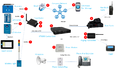
System Architecture

| What is the VT3000 System |
| The VT3000 System is made up of a variety of pieces. Which pieces exist in your system can depend entirely on what was purchased. The one piece that is a requirement for every system is the Control Unit. The Control Unit is the “brain” of the VT3000 system. In addition, there can be a variety of input modules, etc. |
| 1. Control Unit |
Fundamentally, the VT3000 Control Unit is a Windows machine running the VT3000 software. There are multiple options for the control unit.
VersaCall Provided Control Unit - VersaCall will provide a Control Unit running a desktop version of Windows. It will use quality and tested hardware. Customer Provided Control Unit - If a customer would prefer, they can provide the hardware for the system. Some companies for example prefer to only use Dell or HP computers with their own Windows image. Virtual Control Unit - There is the option to create a virtual Control Unit through VMWare or some other form of virtualization. This would all be provided by the customer. This virtual system should still exist on the same network as everything else, meaning that it is not recommended to utilize an “off-site” virtual server. It is important to note there are a couple of limitations with a virtual Control Unit such as: need to use remote versions of coordinators and paging transmitters, no phone support, no Two-Way Radio support. Operating System - the Control Unit is a Windows based system. There are a variety of operating systems that can be used. NOTE: A VersaCall provided Control Unit, only desktop/Professional versions of operating systems are available. Any server versions will need to be provided by the customer. Windows 7 Professional
Windows 10 Professional
Server 2008 R2
Server 2012
Server 2014
Server 2016
Minimum Requirements - Click Here for Control Unit requirements - PC, Server & Virtual Server. Static IP Address - It is highly recommended that you provide the Control Unit with a static IP address (or at least a DHCP reserved one). This makes it more consistent when providing links to the system without the danger of the Control Unit’s IP address changing. Webserver - All the user interfaces for the VT3000 software are web based. This means that the VT3000 Control Unit needs to run Internet Information Services (IIS). Software Dependencies - The VT3000 software was is based on Microsoft.NET meaning that it needs the .NET Framework to operate. Any VT3000 system will need Microsoft.NET 4.6 or newer to run. SLQ Server - The VT3000 system stores its configuration and any captured events into SQL Server databases. There can be up to 8 databases used by the VT3000. Due to cost considerations, the VT3000 system software typically would use an Express version of SQL Server. SQL Server Express would be installed locally on the Control Unit. The VT3000 software supports SQL Server 2008 or newer. If you want, you can either install a full version of SQL Server on the Control Unit or else point the Control Unit at an existing SQL Server instance. If using an existing SQL Server instance, it is recommended that this instance exists on the local network and not at a different location (say the company headquarters). |
| 2. Mesh Network |
| The VT3000 system can utilize a variety of mesh devices: Call Stations, BSC Modules, Production Status Modules, Touch Input Modules, Wireless Switch Contact Modules, Wireless Lights, Wireless Audio Modules, etc. These devices all communicate on the mesh network. The mesh network is a proprietary technology (not to be confused with Wi-Fi or 802.11) that is loosely based on Zigbee (IEEE 802.15.4). It is a self-building mesh network meaning that as more devices are added to it, the coverage of that network is increased. It operates in the 920-928 MHz band. Indoors we typically can get about 400-500 feet per hop of coverage. A “hop” being the distance from one device to the next. A repeater can be utilized to increase coverage range. A repeater has a higher gain antenna and typically will be mounted in a better location than your typical devices allowing a better range of coverage. All a repeater requires is a standard power outlet. |
| 3. Coordinators |
| For the system to communicate over the mesh network, it needs a Coordinator. A Coordinator is basically a 900 MHz radio. Typically, a Coordinator is a USB device that would be connected to the Control Unit. It also requires power through a standard power outlet. |
| 4. Remote Coordinators |
| There is the option to do what we refer to as a Remote Coordinator. This utilizes a Serial-Over-Ethernet device to allow us to position the coordinator anywhere we want and connect it to the Control Unit through a TCP connection over the network. Remote Coordinators require a static IP address (or at least DHCP reserved). Remote Coordinators allow us to add multiple Coordinators to a system, this could be used for example to cover a building a mile down the road. Some considerations need to be addressed when using multiple Coordinators on a single system. |
| 5. Paging Transmitters |
| Another add-on option for a VT3000 system is an on-site paging transmitter. This allows the system to send messages to pagers near the system. Typically, a Paging Transmitter is a USB device that would be connected to the Control Unit. It also requires power though as standard power outlet. |
| 6. Remote Paging Transmitter |
| Like a Remote Coordinator, it is possible to do the same thing with a paging transmitter. Position it anywhere and have the Control Unit talk to it through the network. Remote paging transmitters make it possible to add multiple paging transmitters to increase coverage on a large site. Some care needs to be taken in positioning these paging transmitters though. |
| 7. Phone Communications |
| An add-on module to the VT3000 system, allows it to communicate over a phone line. This makes the system capable of dialing a phone number or extension and synthesizing text to speech or playing a pre-recorded audio message. The most common use of this is to communicate through a PA system. This option requires that an analog phone line is provided. This option is not available on a Virtual Control Unit since the add-on module is a USB device. |
| 8. Two-Way Radios |
| To utilize Two-Way Radio communication, an add on module needs to be purchased. This module consists of a Mobile radio. This radio needs to be programmed up with all the same channel information as your handheld radios (TX/RX Frequencies, DPL Codes, Color Codes, Repeater/Time Slots, etc.). This information is needed prior to shipment so VersaCall can program it in. VersaCall supports both analog and digital radios. |
| 9. PC Modules |
| VersaCall has a line of products designated as “PC Modules”. Currently that lineup includes: PC Call Stations, PC BSC Modules and PC Input Modules. These PC Modules are fundamentally a web page. They could be accessed from a PC or tablet through a specific URL pointing to the Control Unit. VersaCall has a Windows based client application that can be installed on the operator’s machine that makes it a little easier for the operator to access the PC Module. |
| 10. Virtual Panels |
| VersaCall’ s Virtual Panels software allows the creation of real time panels to be created and shown in a variety of locations. These typically show active issues and production metrics but can really be tailored to a customer’s specific needs. Fundamentally, these panels get delivered as a web page. |
| 11. Mini-PCs |
| To show a panel on a TV, something needs to drive it. In lieu of putting out a dedicated Windows PC connected to the TV, VersaCall provides an alternative solution. This comes in the form of what we refer to as a Mini-PC. The Mini-PC is a single board computer running the Windows 10 IoT Core operating system. It has a dedicated application whose job is to talk to the Control Unit and display panels. These Mini-PCs can be connected via Ethernet or Wi-Fi. Whatever network is utilized they need to be able to communicate with the Control Unit. |
| 12. Email/Text Messages |
| The system sends out email and text messages using SMTP. For it to work, you need to provide the system with the address for your email server or SMTP relay. The system can send either anonymous or authenticated SMTP. If using anonymous, it is commonly a requirement to put the Control Unit’s address in the “whitelist” on your email server so it doesn’t reject the email. |
| 13. Backup |
| We leave it up to the customer to backup all files and databases. |
| 14. Anti-Virus |
| We leave it up to the customer to install and maintain any anti-virus software. |
| 15. Stand-Alone System |
| It is possible to do a stand-alone system though typically is not recommended. In this case if the system isn’t connected to a network it will have some limitations. No email/text message communications. Employees won’t be able to run reports and see panels from their computers. Utilizing Virtual Panels can be very limited as there isn’t a network to facilitate a connection from the Mini-PCs to the Control Unit. Though a single TV could be connected directly to the Control Unit. |
Step by Step Guides

Having Trouble?

Submit a Service Ticket