VT3000 - Add Indicators (PSM)
Indicators are small icons that display on the top row of a PSM touch screen. These indicators can be configured in a number of different ways. This guide will show how to turn an indicator on based on the state of an alarm. To complete this guide you must have a PSM along with AMS software installed and licensed.
Indicator Setup
1. Open the VT3000 web interface – log in - select Configuration – select Devices.
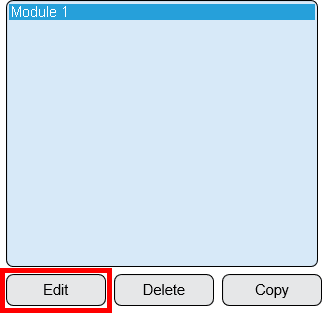
2. Existing PSM - select the PSM from the list - select the Edit button.
3. New PSM - select the Product Status Module icon under the Add New menu.
4. Select the Virtual Indicators tab.
5. Icons in the Indicator Tool Box.
![]() - copy an indicator to the clipboard.
- copy an indicator to the clipboard.
![]() - paste an indicator from the clipboard.
- paste an indicator from the clipboard.
![]() - move an indicator up or down in the list.
- move an indicator up or down in the list.
6. Select to Add an Indicator.
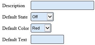
7. Indicator Properties:
    a. Description – text will show below the indicator icon on the PSM.
    b. Default State – select what the indicator will do when nothing has occurred.
         i. Off – indicator will show with no color.
         ii. On – indicator will show with the color selected.
         iii. Blinking – indicator will blink.
         iv. Hidden – indicator will not show on the PSM.
    c. Default Color – select the colort the indicator will be on the PSM.
    d. Default Text – text will show inside the indicator icon when it is not hidden.
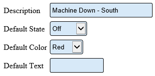
8. For our example, we will be showing a machine down alarm from another device. The indicator will be off when the alarm is cleared snd will show as Red when the alarm is set.
9. Select the Save & Exit button.
Indicator Condition:
A trigger in AMS must be created to turn the indicator on or off.
1. Open the AMS web interface – select Triggers.
2. Select Monitor button.
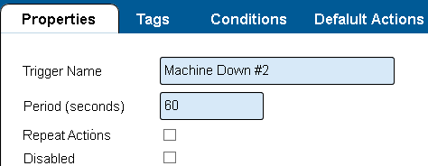
3. Trigger Properties:
    a. Trigger Name - enter a name for the tigger.
    b. Period (seconds) - enter a time, in seconds, before the trigger repeats - 60 for this example.
    c. Repeat Actions - leave box unmarked.
    d. Disabled - leave box unmarked.
13. Select the Tags tab.
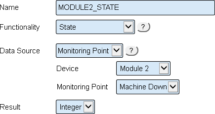
14. Trigger - Tags:
    a. Name - enter a name for the tag.
    b. Functionality - select State.
    c. Data Source - select Monitoring Point.
    d. Device - select the device with the machine down alarm.
    e. Monitoring Point - select the Machine Down alarm.
    d. Result - select Integer.
15. Select the Conditions tab - select the Plus icon from the conditions tool box.
16. Trigger - Conditions
    a. Field 1 - enter the name of the tag created using a tilde symbol first.
    b. Operator - select the less greater than symbol.
    c. Field 2 - enter the number zero.
    d. Action - click on the Add Action button.
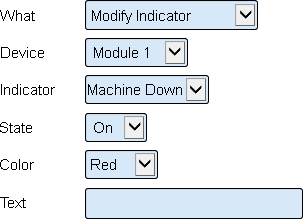
17. Trigger - Action
    a. What -  select Modify Indicator.
    b. Device - select the device that the indicators were added to in Step 6.
    c. Indicator - select the indicator.
    d. State - select On.
    e. Color - select Red.
    f. Text - leave the field blank.
18. Click on the Plus button in the Conditions tool box.
19. Trigger - Conditions
    a. Field 1 - enter the name of the tag created using a tilde symbol first.
    b. Operator - select the equals symbol.
    c. Field 2 - enter the number zero.
    d. Action - click on the Add Action button.
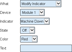
20. Trigger - Action
    a. What -  select Modify Indicator.
    b. Device - select the device that the indicators were added to in Step 6.
    c. Indicator - select the indicator.
    d. State - select Off.
    e. Color - select Red.
    f. Text - leave the field blank.
21. Click on the Save & Exit button.
NOTE: The triggers that have been setup look at the state of the Machine Down alarm on Module 2 and show the results of that state on Module 1 indicators. If the alarm is active the indicator is red. If the alarm is not active the indicator is greyed out.
Update The Device:
1. Update Configuration - PSM - (VT3000)
2. Once the update is complete, the indicator will appear on the touch screen.
Testing the Setup:
1. Activate the Machine Down alarm on Module 2 (for this example). The indicator light on Module 1 (PSM) will now show as red.
2. Deactivate the Machine Down alarm on Module 2 – the indicator light on Module 1 will now be unlit.


