Difference between revisions of "VT3000 - Setup Attached Light Stack - Call Station"
SupportAdmin (talk | contribs) |
SupportAdmin (talk | contribs) |
||
| Line 15: | Line 15: | ||
'''1.''' Open the VT3000 web interface – log in – select Configuration – select Devices. | '''1.''' Open the VT3000 web interface – log in – select Configuration – select Devices. | ||
[[File:3137_1.png]] - [[File:3137_2.png]] | [[File:3137_1.png|border]] - [[File:3137_2.png|border]] | ||
'''2.''' Select the Call Station from the list – select Edit. | '''2.''' Select the Call Station from the list – select Edit. | ||
[[File:3137_3.png]] | [[File:3137_3.png|border]] | ||
'''3.''' Select the Discrete Outputs tab. | '''3.''' Select the Discrete Outputs tab. | ||
[[File:3137_4.png]] | [[File:3137_4.png|border]] | ||
'''4.''' Select Discrete Output 1. | '''4.''' Select Discrete Output 1. | ||
[[File:3137_5.png]] - [[File:3137_6.png]] | [[File:3137_5.png|border]] - [[File:3137_6.png|border]] | ||
'''5.''' Discrete Output Properties: | '''5.''' Discrete Output Properties: | ||
[[File:3137_7.png]][[File:3137_8.png]] | [[File:3137_7.png|border]] - [[File:3137_8.png|border]] | ||
| Line 52: | Line 52: | ||
''6.''' Example - all lights excluding Green: | '''6.''' Example - all lights excluding Green: | ||
[[File:3141_10.png]][[File:3141_11.png]][[File:3141_12.png]][[File:3141_13.png]] | [[File:3141_10.png|border]][[File:3141_11.png|border]][[File:3141_12.png|border]][[File:3141_13.png|border]] | ||
| Line 68: | Line 68: | ||
'''7.''' Example - Green light only: | '''7.''' Example - Green light only: | ||
[[File:3141_14.png]] | [[File:3141_14.png|border]] | ||
| Line 81: | Line 81: | ||
'''10.''' Select Save & Exit. | '''10.''' Select Save & Exit. | ||
[[File:3141_15.png]] | [[File:3141_15.png|border]] | ||
| Line 88: | Line 88: | ||
'''1.''' Select a Call Station with lights attached & set up – select Edit. | '''1.''' Select a Call Station with lights attached & set up – select Edit. | ||
[[File:3137_15.png]] | [[File:3137_15.png|border]] | ||
'''2.''' Select the Monitoring Points tab. | '''2.''' Select the Monitoring Points tab. | ||
[[File:3137_16.png]] | [[File:3137_16.png|border]] | ||
'''3.''' Select the first alarm/button so that it is highlighted. | '''3.''' Select the first alarm/button so that it is highlighted. | ||
[[File:3137_17.png]] - [[File:3137_18.png]] | [[File:3137_17.png|border]] - [[File:3137_18.png|border]] | ||
'''4.''' Select the Actions tab. | '''4.''' Select the Actions tab. | ||
[[File:3137_19.png]] | [[File:3137_19.png|border]] | ||
'''5.''' By default, a Call Station will have actions created | '''5.''' By default, a Call Station will have actions created: | ||
[[File:3137_20.png|border]] | |||
'''a. Set – Blink Red Light''' – on Set output 1/Red will blink. | '''a. Set – Blink Red Light''' – on Set output 1/Red will blink. | ||
| Line 112: | Line 115: | ||
'''c. Clear – Turn off Red Light''' – on Clear output 1/Red will turn off. | '''c. Clear – Turn off Red Light''' – on Clear output 1/Red will turn off. | ||
6. | '''6.''' Action Properties - this window will show when selecting to add or edit an action. | ||
[[File:3137_22.png|border]] | |||
a. State – | '''a. State''' – select state of the alarm Set, Acknowledge or Clear to initiate the action. | ||
b. Type – | '''b. Type''' – 3 options. | ||
i. Modify Discrete Output – | '''i. Modify Discrete Output''' – select an output on the device being configured. | ||
ii. Modify Discrete Output on Another Device – | '''ii. Modify Discrete Output on Another Device''' – select an output on a device other than the one being configured. | ||
c. Action – | '''c. Action''' – select Turn On, Blink or Turn Off. | ||
d. Output – select the output/light | '''d. Output''' – select the output/light for the action. | ||
'''7.''' Select Save & Exit. | |||
[[File:3137_23.png|border]] | |||
Revision as of 18:42, 31 May 2017
This guide explains how to setup wired lights that are attached to the device. If you are trying to setup a wireless light module please see Configure a Wireless Light Module - (VT3000).
The example shown in the guide is for a 5 color light stack attached to a Call Station. Color stack light order is Green at the top then Red, Amber, Blue and White. Green is wired to O5, Red to O1, Amber to O2, Blue to O3 and White to O4. This wired setup is the same on an IO module for a PSM, TIM or BSC. The instructions below will also be the same for any alarms setup on a PSM, TIM or BSC.
Discrete Output Setup
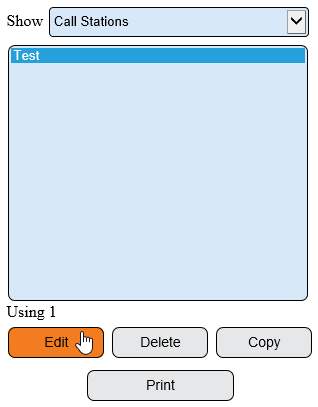
1. Open the VT3000 web interface – log in – select Configuration – select Devices.
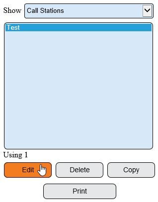
2. Select the Call Station from the list – select Edit.
3. Select the Discrete Outputs tab.
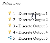
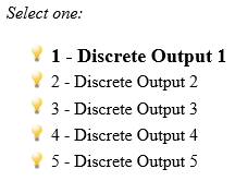
4. Select Discrete Output 1.
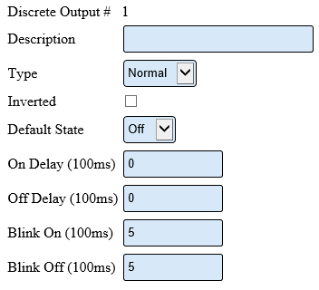
5. Discrete Output Properties:
    a. Description – enter a name for the output – light color.
    b. Type – 3 options:
         i. Normal – output will turn on/off when commanded.
         ii. Disabled – output will not turn on/off.
         iii. Related – output will turn on/off when another output is on/off.
    c. Inverted – output will do the opposite of normal.
    d. On Delay – number of milliseconds to elapse before the output turns on.
    e. Off Delay – number of milliseconds to elapse before the output turns off.
    f. Blink On – number of milliseconds to stay on during blink.
    g. Blink Off – number or milliseconds to stay off during blink.
    h. Direct – available when Related Type is selected. Not applicable.
    i. Inverse – available when Related Type is selected. Explained in Step 8.
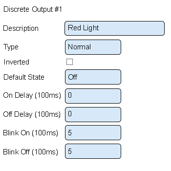
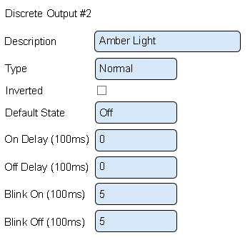
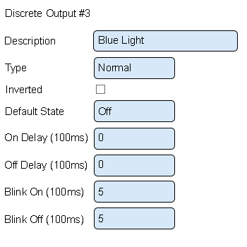
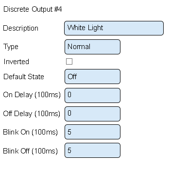
6. Example - all lights excluding Green:
    a. Description – enter the light color.
    b. Type – leave this as normal.
    c. Inverted – leave this unchecked.
    d. Default State – select Off.
    e. On Delay – enter Zero.
    f. Off Delay – enter Zero.
    g. Blink On – enter 5.
    h. Blink Off – enter 5.
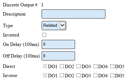
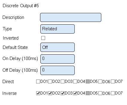
7. Example - Green light only:
    a. Description – enter Green Light.
    b. Type – select Related.
    c. Inverted – leave this unchecked.
    d. On Delay – leave this set to zero.
    e. Off Delay – leave this set to zero.
    f. Direct – leave all unchecked.
    g. Inverse – mark DO1, DO2, DO3 and DO4.
10. Select Save & Exit.
Actions Setup: - devices use Actions to turn on, blink and turn off lights.
1. Select a Call Station with lights attached & set up – select Edit.
2. Select the Monitoring Points tab.
3. Select the first alarm/button so that it is highlighted.
4. Select the Actions tab.
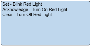
5. By default, a Call Station will have actions created:
    a. Set – Blink Red Light – on Set output 1/Red will blink.
    b. Acknowledge – Turn on Red Light – on Acknowledge output 1/Red will turn on.
    c. Clear – Turn off Red Light – on Clear output 1/Red will turn off.
6. Action Properties - this window will show when selecting to add or edit an action.
    a. State – select state of the alarm Set, Acknowledge or Clear to initiate the action.
    b. Type – 3 options.
         i. Modify Discrete Output – select an output on the device being configured.
         ii. Modify Discrete Output on Another Device – select an output on a device other than the one being configured.
    c. Action – select Turn On, Blink or Turn Off.
    d. Output – select the output/light for the action.
7. Select Save & Exit.


