VT3000 - Setup Attached Light Stack - Call Station

From Versacall Support
Jump to navigation Jump to search
Call Now 858-677-6766 SubmitTckBtn.png EmailUsBtn.png


GeneralHeader.png

Overview
This guide explains how to setup the output connections to control a light stack that is attached/wired to a Call station. The example shown in the guide is for a 5 color light stack attached to a Call Station. Regardless of how many lights you have in your stack, the instructions will be exactly the same.


Requirements
See Requirements Here
1. The VT3000 Core Software installed and running on your system.
2. A Coordinator must be setup, powered and communicating with the VT3000 Core Software.
3. A Powered Call Station w/Light Stack attached communicating with the VT3000 Software.
4. A Call Station Configuration setup in the VT3000 Software.


Completion Steps
LightPart1.png LightPart2A.png LightPart3.png


InstructionHeader.png

Step 1.
Open the VT3000 web interface – select VT3000 Core Software - log in – select Configuration – select Devices.
3137 1.png
3137 2.png
Configuration Devices


Step 2.
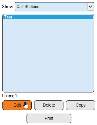
Select the Configuration of the Call Station with a Light Stack attached from the list – select Edit.
3137 3.png


Step 3.
Select the Discrete Outputs tab.
3137 4.png


Step 4.
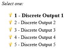
Select Discrete Output 1.
3137 6.png


Step 5.
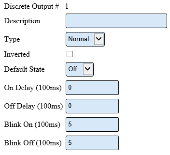
Discrete Output Properties
3137 7.png
Description – enter a name for the output – light color.
Type – Normal – output will turn on/off when commanded.
Inverted – output will do the opposite of normal.
Default State - what behavior the output will perform when it has no command.
On Delay – number of milliseconds to elapse before the output turns on.
Off Delay – number of milliseconds to elapse before the output turns off.
Blink On – number of milliseconds to stay on during blink.
Blink Off – number or milliseconds to stay off during blink.


Step 6.
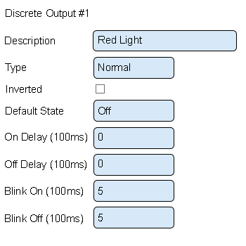
Setup Discrete Output 1 as the Red Light. This is done because the Red Light is wired into O1 on the Call Station.
3141 10.png
Description – enter Red Light.
Type – leave this as normal.
Inverted – leave this unchecked.
Default State – select Off.
On Delay – leave this as Zero.
Off Delay – leave this as Zero.
Blink On – leave this as 5.
Blink Off – leave this as 5.


Step 7.
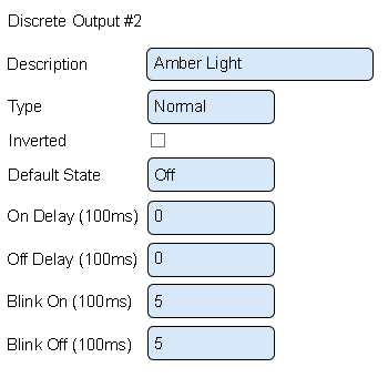
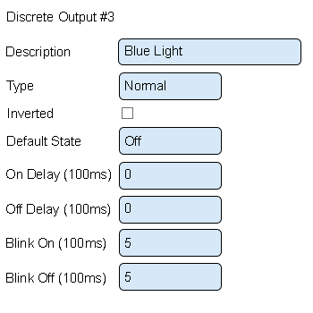
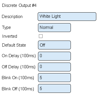
Setup the other lights in the exact same manner - only the Output Description will change. Examples of each light setup is shown below. Please use the Exact same order that we have shown below as this will match up with the way your Call Station has been wired.
3141 11.png
3141 12.png
3141 13.png


Step 8.
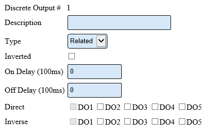
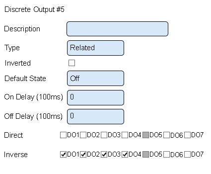
The Green light is setup to do the opposite of each of the other lights. For this reason, the Green light configuration is setup differently - we use a Related Type. The image below shows the options available for a Related Type:
3137 8.png
Description – enter a name for the output – light color.
Type – Related – output will turn on/off when another selected output is on/off.
Inverted – output will do the opposite of normal.
On Delay – number of milliseconds to elapse before the output turns on.
Off Delay – number of milliseconds to elapse before the output turns off.
Direct – output will do the exact same behavior as another selected output.
Inverse – output will do the opposite behavior as another selected output.


Step 9.
Discrete Output 5 Properties;
3141 14.png
Description – enter Green Light.
Type – select Related.
Inverted – leave this unchecked.
On Delay – leave this as zero.
Off Delay – leave this as zero.
Direct – leave these all unchecked.
Inverse – check mark DO1, DO2, DO3 and DO4. This tells the Green light to do the opposite of the other lights.


Step 10.
Select Save & Exit to save the setup - proceed to Step 3.
3141 15.png


RelatedHowTos.png
Select a Guide Here
Installation Instructions for a Battery Call Station
Installation Instructions for a Powered Call Station
Add a Call Station Configuration
Update the Configuration on a Battery Call Station
Update the Configuration on a Powered Call Station
Update the Firmware on a Battery Call Station - Wireless
Update the Firmware on a Powered Call Station - Wireless
Update the Firmware on a Call Station - Manually
Install/Attach a Stack Light to a Call Station
Setup the Use of the Light(s) on the Call Station Configuration
Change ISO Code on a Call Station using the # 1 - # 4 Buttons
Change ISO Code on a Call Station using the Micro SD Card
Change ISO Code on a Call Station using VT3000 Core Software Wirelessly
Perform a Coverage Test on a Powered Call Station
Perform a Coverage Test on a Battery Powered Call Station


SearchHeader.png


VC Footer.png
Follow Us On LinkedIn View our Blog