Difference between revisions of "VT3000 - Install Paging Transmitter - Remote - Different Subnet"
SupportAdmin (talk | contribs) |
SupportAdmin (talk | contribs) |
||
| Line 79: | Line 79: | ||
''' | '''10.''' Leave the Password blank – select the Login button. | ||
[[File:3103_3.png]] | [[File:3103_3.png]] | ||
''' | '''11.''' Enter any name to identify the transmitter – select the Next button. | ||
[[File:3103_4.png]] | [[File:3103_4.png]] | ||
''' | '''12.''' Enter IP address information provided by your IT department – select the Next button. | ||
[[File:3103_5.png]] | [[File:3103_5.png]] | ||
''' | '''13.''' Use the settings below. | ||
[[File: | [[File:trans16.png]] | ||
'''a. Network Protocol''' – select TCP – select “to wait for connections”. | '''a. Network Protocol''' – select TCP – select “to wait for connections”. | ||
| Line 103: | Line 103: | ||
'''d. IP Address''' – enter the IP address of the VersaCall computer. | '''d. IP Address''' – enter the IP address of the VersaCall computer. | ||
'''NOTE:''' The IP address shown in the image is for reference purposes - use the IP address of your VersaCall computer/server. | |||
'''14.'''Select the Advanced button. | |||
[[File:3103_7.png]] | [[File:3103_7.png]] | ||
''' | '''15.''' Use the settings below. | ||
[[File:3103_8.png]] | [[File:3103_8.png]] | ||
| Line 118: | Line 121: | ||
'''d. Data Packets''' – do not select the option to control data packets. | '''d. Data Packets''' – do not select the option to control data packets. | ||
'''16.''' Select the Next button. | |||
[[File:3103_9.png]] | [[File:3103_9.png]] | ||
''' | '''17.''' Use the settings below: | ||
[[File:3103_10.png]] | [[File:3103_10.png]] | ||
| Line 135: | Line 139: | ||
'''g. Flow Control''' – select No Flow Control | '''g. Flow Control''' – select No Flow Control | ||
'''18.''' Select the Next button. | |||
[[File:3103_9.png]] | [[File:3103_9.png]] | ||
''' | '''19.''' Select the Save button. | ||
[[File:3103_11.png]] | [[File:3103_11.png]] | ||
''' | '''20.''' Go to the VersaCall Computer - open the VT3000 home page - select Administration – System Settings – Service. | ||
<gallery widths=150> | |||
File:HT3100_2.png | |||
File:HT3100_3.png | |||
File:HT3100_4.png | |||
</gallery> | |||
''' | '''21.''' Select the Paging Transmitter tab – select the add “+” icon. | ||
[[File:3103_18.png]] | [[File:3103_18.png]] | ||
''' | '''22.''' Use the settings below: | ||
[[File:3103_19.png]] | [[File:3103_19.png]] | ||
| Line 177: | Line 176: | ||
'''g. Port''' – enter 4000. | '''g. Port''' – enter 4000. | ||
''' | |||
'''23.''' Click on the Save & Exit button in the top right corner of the screen. | |||
[[File:3103_20.png]] | [[File:3103_20.png]] | ||
''' | '''24.''' Select Yes on the Restart warning message. This must be done to complete the setup. | ||
[[File: | [[File:3102_22.png]] | ||
'''25.''' Restart the VersaCall Service - [[VT3000 - Restart Service|'''Click here for Instructions''']]. | |||
[[File:3102_25.png]] | |||
''' | '''26.''' Test the Transmitter - [[VT3000_-_Test_-_Pager_Coverage|'''Click here for Instructions''']]. | ||
If are having trouble, contact [https://www.versacall.com/customer-support/service-ticket/ <u>'''VersaCall Support'''</u>] for further assistance. | |||
Revision as of 19:08, 14 June 2018
Overview
This guide will show how to configure a remote transmitter that is on a different subnet than the VersaCall computer/server. For this method, you must have the IP address of the port that the RS232 device is plugged into – consult your IT department for this information. They may need to trace the device using the MAC address, this is printed on a label attached to the bottom of the RS-232 device. IT will also need to provide a static IP address that can be used for this device.
Unpack
You will have the following components after unpacking.

Paging Transmitter

Power Cord

Serial Cable

Antenna
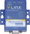
RS-232
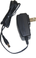
RS-232 Power

Serial Cable


Instructions
1. Connect the Serial Cable to the port on the Transmitter.

2. Connect the other end of the Serial Cable to the RS-232 device.

3. Connect the Power Cable to the Paging Transmitter.

4. Connect the Antenna to the Paging Transmitter.

5. Connect the Power Cable to the RS-232 device.

6. Connect the Ethernet Cable to the RS-232 device.

7. Connect the Ethernet Cable to your available port.

8. Connect both Power Cables to an Electrical Outlet.

9. Open a web browser (IE, Firefox or Chrome) – enter the IP address for the port the RS232 device in plugged into or the IP address from the MAC trace.

10. Leave the Password blank – select the Login button.

11. Enter any name to identify the transmitter – select the Next button.

12. Enter IP address information provided by your IT department – select the Next button.

13. Use the settings below.

    a. Network Protocol – select TCP – select “to wait for connections”.
    b. Port Number – enter 4000.
    c. Limit – select 4 connections from the drop down list.
    d. IP Address – enter the IP address of the VersaCall computer.
NOTE: The IP address shown in the image is for reference purposes - use the IP address of your VersaCall computer/server.
14.Select the Advanced button.

15. Use the settings below.

    a. Advanced – click in the box next to “I want to control when connections would be forced to close” to place a check mark in it.
    b. Network – click in the box next to “I want to close a connection” to place a check mark in it.
         i. Select “after the connection ……” and enter 2 in the field for minutes.
    c. Serial – uncheck the box and leave the milliseconds field blank.
    d. Data Packets – do not select the option to control data packets.
16. Select the Next button.
![]()
17. Use the settings below:

    a. Description – enter Serial Port 1
    b. Mode – select RS-232
    c. Baud Rate – select 9600
    d. Data Bits – select 8-Bits
    e. Stop Bits – select 1-Bit
    f. Parity – select No Parity
    g. Flow Control – select No Flow Control
18. Select the Next button.
![]()
19. Select the Save button.

20. Go to the VersaCall Computer - open the VT3000 home page - select Administration – System Settings – Service.


21. Select the Paging Transmitter tab – select the add “+” icon.

22. Use the settings below:

    a. Enabled – click on the box to place a check mark – this will enable the device.
    b. Description – enter any name for the transmitter.
    c. Driver – select the Salcom 12-62 - Remote driver from the list.
    d. Synchronization Code – if installing multiple transmitters, use the different codes.
    e. Connection Method – select TCP Client from the list.
    f. Address – enter the Static IP address that you entered in Step 5.
    g. Port – enter 4000.
23. Click on the Save & Exit button in the top right corner of the screen.

24. Select Yes on the Restart warning message. This must be done to complete the setup.

25. Restart the VersaCall Service - Click here for Instructions.

26. Test the Transmitter - Click here for Instructions.
If are having trouble, contact VersaCall Support for further assistance.