Difference between revisions of "VT3000 - Install 2-Way Radio Module"
SupportAdmin (talk | contribs) |
SupportAdmin (talk | contribs) |
||
| Line 1: | Line 1: | ||
=2-Way Radio Module= | =2-Way Radio Module= | ||
A 2-Way radio module can be purchased for your VersaCall system. This module will attach directly to the VersaCall computer/server using | A 2-Way radio module can be purchased for your VersaCall system. This module will attach directly to the VersaCall computer/server using an LPT port and Audio Out port. If your VersaCall computer/server does not have an existing LPT port, you will need to have one installed before proceeding. Please contact VersaCall Support for questions regarding this module. | ||
| Line 6: | Line 6: | ||
You will have the following components after unpacking. | You will have the following components after unpacking. | ||
<gallery widths= | <gallery widths=248 heights=395> | ||
File:InstallRadio1.png|Radio Unit | File:InstallRadio1.png|Radio Unit | ||
</gallery> | </gallery> | ||
| Line 16: | Line 15: | ||
'''1.''' Mount the radio module cabinet within 6 feet of the VersaCall computer/server and within 6 feet of a 110 electrical outlet. | '''1.''' Mount the radio module cabinet within 6 feet of the VersaCall computer/server and within 6 feet of a 110 electrical outlet. | ||
<gallery widths=300> | <gallery widths=300 heights=92> | ||
File:Rado1.png | File:Rado1.png | ||
</gallery> | |||
<gallery widths=300 heights=104> | |||
File:Rado2.png | File:Rado2.png | ||
</gallery> | </gallery> | ||
'''2.''' Connect the LPT cable to the VersaCall computer/server. | '''2.''' Connect the LPT cable to the VersaCall computer/server. | ||
<gallery widths=300> | <gallery widths=300 heights=94> | ||
File:Radio7.png | File:Radio7.png | ||
</gallery> | </gallery> | ||
'''3.''' Connect the Audio cable to the VersaCall computer/server. | '''3.''' Connect the Audio cable to the VersaCall computer/server. | ||
<gallery widths=300> | <gallery widths=300 heights=94> | ||
File:Radio8.png | File:Radio8.png | ||
</gallery> | </gallery> | ||
'''4.''' Plug the radio module cabinet into an electrical outlet. | '''4.''' Plug the radio module cabinet into an electrical outlet. | ||
<gallery widths=300> | <gallery widths=300 heights=121> | ||
File:Rado3.png | File:Rado3.png | ||
</gallery> | </gallery> | ||
'''5.''' Open the VT3000 web interface - select Core Software - Administration - System Settings - Service. | '''5.''' Open the VT3000 web interface - select Core Software - Administration - System Settings - Service. | ||
<gallery widths= | <gallery widths=93 heights=93> | ||
File:3122_10.png | File:3122_10.png | ||
File:3122_11.png | File:3122_11.png | ||
File:3122_12.png | File:3122_12.png | ||
</gallery> | </gallery> | ||
'''6.''' Select Audio Out tab. | '''6.''' Select Audio Out tab. | ||
<gallery widths= | <gallery widths=545 heights=41> | ||
File:Radio9.png | File:Radio9.png | ||
</gallery> | </gallery> | ||
'''7.''' The following settings are needed to make the Radio module work with the system. | '''7.''' The following settings are needed to make the Radio module work with the system. | ||
<gallery widths= | <gallery widths=325 heights=144> | ||
File:Radio10.png | File:Radio10.png | ||
</gallery> | </gallery> | ||
| Line 70: | Line 77: | ||
'''8.''' Select Yes on the Restart warning message. This must be done to complete the setup. | '''8.''' Select Yes on the Restart warning message. This must be done to complete the setup. | ||
<gallery widths=402 heights=178> | |||
File:3102_22.png | |||
</gallery> | |||
| Line 85: | Line 94: | ||
'''1.''' Open the VT3000 web interface - select Core Software - Administration - System Settings - Service. | '''1.''' Open the VT3000 web interface - select Core Software - Administration - System Settings - Service. | ||
<gallery widths= | <gallery widths=93 heights=93> | ||
File:3122_10.png | File:3122_10.png | ||
File:3122_11.png | File:3122_11.png | ||
File:3122_12.png | File:3122_12.png | ||
</gallery> | </gallery> | ||
'''2.''' Select Audio Out tab. | '''2.''' Select Audio Out tab. | ||
<gallery widths= | <gallery widths=545 heights=41> | ||
File:Radio9.png | File:Radio9.png | ||
</gallery> | </gallery> | ||
'''3.''' Change the Port setting to LPT2. | '''3.''' Change the Port setting to LPT2. | ||
<gallery widths= | <gallery widths=322 heights=144> | ||
File:Radio13.png | File:Radio13.png | ||
</gallery> | </gallery> | ||
| Line 106: | Line 117: | ||
'''4.''' Select Yes on the Restart warning message. This must be done to complete the setup. | '''4.''' Select Yes on the Restart warning message. This must be done to complete the setup. | ||
<gallery widths=402 heights=178> | |||
File:3102_22.png | |||
</gallery> | |||
| Line 121: | Line 134: | ||
'''1.''' Double check all connections. | '''1.''' Double check all connections. | ||
<gallery widths= | <gallery widths=300 heights=94> | ||
File:Radio7.png | File:Radio7.png | ||
File:Radio8.png | File:Radio8.png | ||
</gallery> | |||
<gallery widths=300 heights=121> | |||
File:Rado3.png | File:Rado3.png | ||
</gallery> | </gallery> | ||
| Line 129: | Line 144: | ||
'''a. LPT Cable''' - securely plugged into the VersaCall computer/server via LPT Port. | '''a. LPT Cable''' - securely plugged into the VersaCall computer/server via LPT Port. | ||
'''b. Audio Cable''' - plugged into the correct port on the VersaCall computer/server. | '''b. Audio Cable''' - plugged into the correct port on the VersaCall computer/server. | ||
'''c. Power Cord''' - | '''c. Power Cord''' - radio module plugged into a working electrical outlet. | ||
'''2.''' On the VersaCall computer select - Windows Start button - Control Panel - Device Manager. | '''2.''' On the VersaCall computer select - Windows Start button - Control Panel - Device Manager. | ||
| Line 140: | Line 156: | ||
File:Rado10.png|Device Manager (10) | File:Rado10.png|Device Manager (10) | ||
</gallery> | </gallery> | ||
'''3.''' Select to expand the Ports (COM & LPT) section. | '''3.''' Select to expand the Ports (COM & LPT) section. | ||
<gallery widths= | <gallery widths=153 heights=22> | ||
File:Radio1.png | File:Radio1.png | ||
</gallery> | </gallery> | ||
'''4.''' Select the first LPT port in the list - so that it is highlighted. | '''4.''' Select the first LPT port in the list - so that it is highlighted. | ||
<gallery widths= | <gallery widths=258 heights=89> | ||
File:Radio2.png | File:Radio2.png | ||
</gallery> | </gallery> | ||
'''5.''' Select Action - Properties. | '''5.''' Select Action - Properties. | ||
<gallery widths= | <gallery widths=269 heights=235> | ||
File:Radio3.png | File:Radio3.png | ||
</gallery> | </gallery> | ||
'''6.''' Select the Resources tab. | '''6.''' Select the Resources tab. | ||
<gallery widths= | <gallery widths=281 heights=45> | ||
File:Radio4.png | File:Radio4.png | ||
</gallery> | </gallery> | ||
'''7.''' In the Resource Settings section there will be 2 I/O Range settings. Take note of the first number in each range (E010 & E000 in our example below). | '''7.''' In the Resource Settings section there will be 2 I/O Range settings. Take note of the first number in each range (E010 & E000 in our example below). | ||
<gallery widths= | <gallery widths=357 heights=94> | ||
File:Radio5.png | File:Radio5.png | ||
</gallery> | </gallery> | ||
'''8.''' Open the VT3000 web interface - select Core Software - Administration - System Settings - Service. | '''8.''' Open the VT3000 web interface - select Core Software - Administration - System Settings - Service. | ||
<gallery widths= | <gallery widths=93 heights=93> | ||
File:3122_10.png | File:3122_10.png | ||
File:3122_11.png | File:3122_11.png | ||
File:3122_12.png | File:3122_12.png | ||
</gallery> | </gallery> | ||
'''9.''' Select Audio Out tab. | '''9.''' Select Audio Out tab. | ||
<gallery widths= | <gallery widths=545 heights=41> | ||
File:Radio9.png | File:Radio9.png | ||
</gallery> | </gallery> | ||
'''10.''' Select DMA for the Port field. Enter the first letter/number range in the field provided. | '''10.''' Select DMA for the Port field. Enter the first letter/number range in the field provided. | ||
<gallery widths= | <gallery widths=287 heights=124> | ||
File:Rado5.png | File:Rado5.png | ||
</gallery> | </gallery> | ||
| Line 194: | Line 218: | ||
'''11.''' Select Yes on the Restart warning message. This must be done to complete the setup. | '''11.''' Select Yes on the Restart warning message. This must be done to complete the setup. | ||
<gallery widths=402 heights=178> | |||
File:3102_22.png | |||
</gallery> | |||
| Line 205: | Line 231: | ||
'''14.''' If there is no sound after testing, open the VT3000 web interface - select Core Software - Administration - System Settings - Service. | '''14.''' If there is no sound after testing, open the VT3000 web interface - select Core Software - Administration - System Settings - Service. | ||
<gallery widths= | <gallery widths=93 heights=93> | ||
File:3122_10.png | File:3122_10.png | ||
File:3122_11.png | File:3122_11.png | ||
File:3122_12.png | File:3122_12.png | ||
</gallery> | </gallery> | ||
'''15.''' Select Audio Out tab. | '''15.''' Select Audio Out tab. | ||
<gallery widths= | <gallery widths=545 heights=41> | ||
File:Radio9.png | File:Radio9.png | ||
</gallery> | </gallery> | ||
'''16.''' Select DMA for the Port field. Enter the second letter/number range in the field provided. | '''16.''' Select DMA for the Port field. Enter the second letter/number range in the field provided. | ||
<gallery widths= | <gallery widths=286 heights=123> | ||
File:Rado6.png | File:Rado6.png | ||
</gallery> | </gallery> | ||
| Line 226: | Line 254: | ||
'''17.''' Select Yes on the Restart warning message. This must be done to complete the setup. | '''17.''' Select Yes on the Restart warning message. This must be done to complete the setup. | ||
<gallery widths=402 heights=178> | |||
File:3102_22.png | |||
</gallery> | |||
| Line 233: | Line 263: | ||
'''19.''' Test the Radio - [[VT3000 - Test - Radio Channel|'''Click here for Instructions''']]. | '''19.''' Test the Radio - [[VT3000 - Test - Radio Channel|'''Click here for Instructions''']]. | ||
Revision as of 15:58, 27 September 2018
2-Way Radio Module
A 2-Way radio module can be purchased for your VersaCall system. This module will attach directly to the VersaCall computer/server using an LPT port and Audio Out port. If your VersaCall computer/server does not have an existing LPT port, you will need to have one installed before proceeding. Please contact VersaCall Support for questions regarding this module.
Unpack
You will have the following components after unpacking.
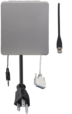
Radio Unit

Instructions
1. Mount the radio module cabinet within 6 feet of the VersaCall computer/server and within 6 feet of a 110 electrical outlet.


2. Connect the LPT cable to the VersaCall computer/server.

3. Connect the Audio cable to the VersaCall computer/server.

4. Plug the radio module cabinet into an electrical outlet.

5. Open the VT3000 web interface - select Core Software - Administration - System Settings - Service.


6. Select Audio Out tab.
7. The following settings are needed to make the Radio module work with the system.

    a. Enabled - check mark the box to enable.
    b. Description - enter a name for the module.
    c. Driver - select one of the following options.
         i. Direct Audio - the audio will be played through the Audio Out port only.
         ii. Vertex Standard VX-4600 - select when setting up a Vertex analog radio.
         iii. Motorola XPR 5000 - select when setting up a Motorola analog or digital radio.
    d. Port - select LPT1.
8. Select Yes on the Restart warning message. This must be done to complete the setup.

9. Restart the VersaCall Service - Click here for Instructions.
10. Test the Radio - Click here for Instructions.
Basic Troubleshooting
If there is no sound playing on the radio channel, proceed with the steps below.
1. Open the VT3000 web interface - select Core Software - Administration - System Settings - Service.
2. Select Audio Out tab.
3. Change the Port setting to LPT2.

4. Select Yes on the Restart warning message. This must be done to complete the setup.
5. Restart the VersaCall Service - Click here for Instructions.
6. Test the Radio - Click here for Instructions.
Advanced Troubleshooting
If there is no sound playing on the radio channel after selecting LPT1 & LPT2, proceed to the following steps. To proceed with the steps below, the user must have direct access to the VersaCall computer/server or be able to use Remote PC to access the VersaCall computer/server.
1. Double check all connections.
         a. LPT Cable - securely plugged into the VersaCall computer/server via LPT Port.
         b. Audio Cable - plugged into the correct port on the VersaCall computer/server.
         c. Power Cord -  radio module plugged into a working electrical outlet.
2. On the VersaCall computer select - Windows Start button - Control Panel - Device Manager.

Windows 7

Windows 10

Control Panel

Device Manager (7)

Device Manager (10)


3. Select to expand the Ports (COM & LPT) section.
4. Select the first LPT port in the list - so that it is highlighted.

5. Select Action - Properties.

6. Select the Resources tab.
7. In the Resource Settings section there will be 2 I/O Range settings. Take note of the first number in each range (E010 & E000 in our example below).

8. Open the VT3000 web interface - select Core Software - Administration - System Settings - Service.
9. Select Audio Out tab.
10. Select DMA for the Port field. Enter the first letter/number range in the field provided.

11. Select Yes on the Restart warning message. This must be done to complete the setup.
12. Restart the VersaCall Service - Click here for Instructions.
13. Test the Radio - Click here for Instructions.
14. If there is no sound after testing, open the VT3000 web interface - select Core Software - Administration - System Settings - Service.
15. Select Audio Out tab.
16. Select DMA for the Port field. Enter the second letter/number range in the field provided.

17. Select Yes on the Restart warning message. This must be done to complete the setup.
18. Restart the VersaCall Service - Click here for Instructions.
19. Test the Radio - Click here for Instructions.
Having Trouble?

Submit a Service Ticket