Difference between revisions of "VT3000 - Install PSM with IO"
Jump to navigation
Jump to search
SupportAdmin (talk | contribs) |
SupportAdmin (talk | contribs) |
||
| Line 15: | Line 15: | ||
'''1.''' Mount IO Module within 6 feet of an electrical outlet. | '''1.''' Mount IO Module within 6 feet of an electrical outlet. | ||
<gallery widths= | <gallery widths=400 heights=240> | ||
File: | File:Install_PSM1.gif | ||
</gallery> | </gallery> | ||
| Line 22: | Line 22: | ||
'''2.''' Attach Touch Screen to the mount using the included screws. | '''2.''' Attach Touch Screen to the mount using the included screws. | ||
<gallery widths= | <gallery widths=400 heights=240> | ||
File: | File:Install_PSM2.gif | ||
</gallery> | </gallery> | ||
| Line 29: | Line 29: | ||
'''3.''' Mount the Touch Screen within 6 feet of an electrical outlet & within 20 feet of the IO Module. | '''3.''' Mount the Touch Screen within 6 feet of an electrical outlet & within 20 feet of the IO Module. | ||
<gallery widths= | <gallery widths=400 heights=240> | ||
File: | File:Install_PSM3.gif | ||
</gallery> | </gallery> | ||
| Line 36: | Line 36: | ||
'''4.''' Find & Note of the Mesh Address on IO Module. - plug in IO Module & the Touch Screen. | '''4.''' Find & Note of the Mesh Address on IO Module. - plug in IO Module & the Touch Screen. | ||
<gallery widths= | <gallery widths=400 heights=240> | ||
File: | File:Install_PSM4.gif | ||
</gallery> | </gallery> | ||
| Line 43: | Line 43: | ||
'''5.''' Plug in the IO Module & Touch Screen power. | '''5.''' Plug in the IO Module & Touch Screen power. | ||
<gallery widths= | <gallery widths=400 heights=240> | ||
File: | File:Install_PSM5.gif | ||
</gallery> | </gallery> | ||
| Line 50: | Line 50: | ||
'''6.''' The IO Module & Touch Screen will automatically connect - verify Bluetooth connection on the Touch Screen. | '''6.''' The IO Module & Touch Screen will automatically connect - verify Bluetooth connection on the Touch Screen. | ||
<gallery widths= | <gallery widths=400 heights=240> | ||
File: | File:Install_PSM6.gif | ||
</gallery> | </gallery> | ||
| Line 57: | Line 57: | ||
'''7.''' Open VT3000 Core Software select Diagnostics - select Device Status. | '''7.''' Open VT3000 Core Software select Diagnostics - select Device Status. | ||
<gallery widths= | <gallery widths=400 heights=240> | ||
File: | File:Install_PSM7.gif | ||
</gallery> | </gallery> | ||
| Line 64: | Line 64: | ||
'''8.''' Find the IO Mesh Address in the Address field - select Options link on the right. | '''8.''' Find the IO Mesh Address in the Address field - select Options link on the right. | ||
<gallery widths= | <gallery widths=400 heights=240> | ||
File: | File:Install_PSM8.gif | ||
</gallery> | </gallery> | ||
| Line 71: | Line 71: | ||
'''9.''' Select Configuration. | '''9.''' Select Configuration. | ||
<gallery widths= | <gallery widths=400 heights=240> | ||
File: | File:Install_PSM9.gif | ||
</gallery> | </gallery> | ||
| Line 78: | Line 78: | ||
'''10.''' Select a Device Configuration from the New Configuration field - select Update Configuration button. | '''10.''' Select a Device Configuration from the New Configuration field - select Update Configuration button. | ||
<gallery widths= | <gallery widths=400 heights=240> | ||
File:Install PSM10.gif | File:Install PSM10.gif | ||
</gallery> | </gallery> | ||
| Line 85: | Line 85: | ||
'''11.''' Go to the Touch Screen - verify the correct module name shows in the top left corner. | '''11.''' Go to the Touch Screen - verify the correct module name shows in the top left corner. | ||
<gallery widths= | <gallery widths=400 heights=240> | ||
File:Install PSM11.gif | File:Install PSM11.gif | ||
</gallery> | </gallery> | ||
Revision as of 16:57, 26 October 2018
Overview
If you have purchased a new PSM for your existing system please follow the steps below. If this is a new system, please ensure that you have the control unit installed with the coordinator operating normally.
Unpack
You will have the following components after unpacking:
Instructions
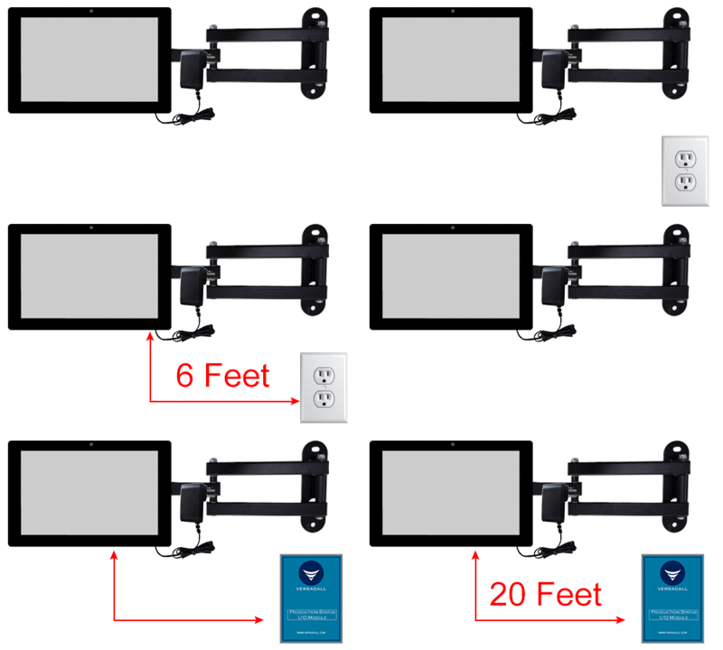
1. Mount IO Module within 6 feet of an electrical outlet.
2. Attach Touch Screen to the mount using the included screws.
3. Mount the Touch Screen within 6 feet of an electrical outlet & within 20 feet of the IO Module.
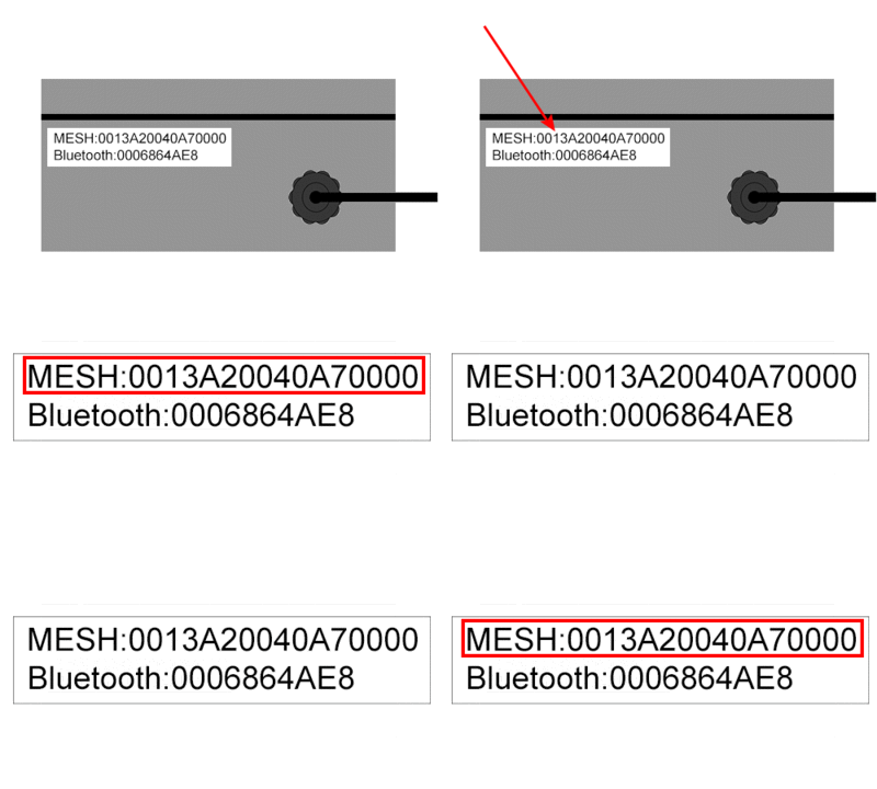
4. Find & Note of the Mesh Address on IO Module. - plug in IO Module & the Touch Screen.
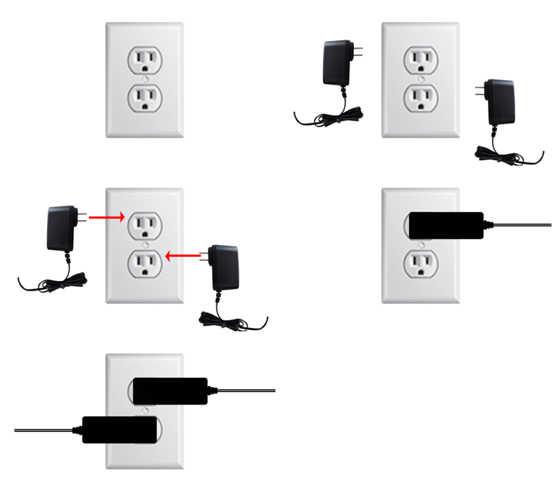
5. Plug in the IO Module & Touch Screen power.
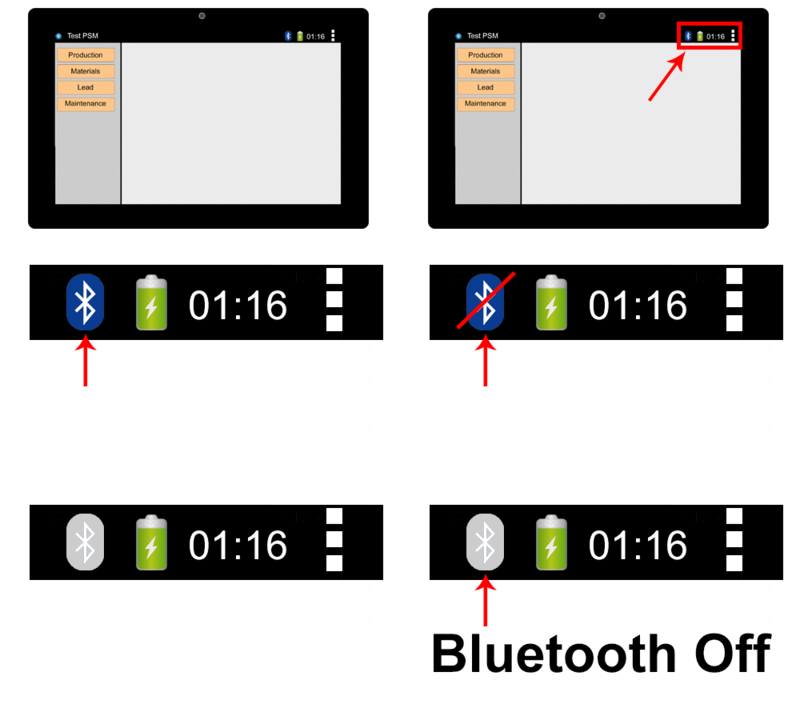
6. The IO Module & Touch Screen will automatically connect - verify Bluetooth connection on the Touch Screen.
7. Open VT3000 Core Software select Diagnostics - select Device Status.
8. Find the IO Mesh Address in the Address field - select Options link on the right.
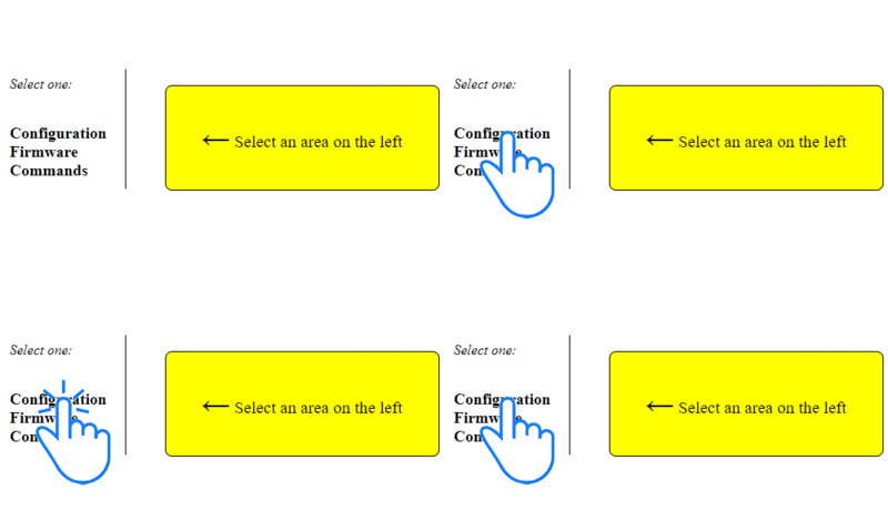
9. Select Configuration.
10. Select a Device Configuration from the New Configuration field - select Update Configuration button.
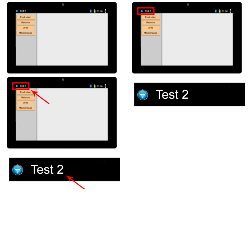
11. Go to the Touch Screen - verify the correct module name shows in the top left corner.
Step by Step Guides
Click Here for a guide on updating the configuration of a BSC, TIM or PSM.


