Difference between revisions of "VT3000 - Install Coordinator - USB"
Jump to navigation
Jump to search
SupportAdmin (talk | contribs) |
SupportAdmin (talk | contribs) |
||
| Line 20: | Line 20: | ||
{| role="presentation" class="wikitable mw-collapsible mw-collapsed" | {| role="presentation" class="wikitable mw-collapsible mw-collapsed" | ||
|<big>'''Step 1:''' | |<big>'''Step 1:''' If your coordinator is powered, disconnect the Power from the outlet.</big> | ||
|- | |- | ||
| <em>[[File:USBCoordinator1.gif|border|400px]]</em> | | <em>[[File:USBCoordinator1.gif|border|400px]]</em> | ||
| Line 34: | Line 34: | ||
{| role="presentation" class="wikitable mw-collapsible mw-collapsed" | {| role="presentation" class="wikitable mw-collapsible mw-collapsed" | ||
|<big>'''Step 3:''' Remove the old coordinator | |<big>'''Step 3:''' Remove the old coordinator. Place new coordinator in the same place, attach the antenna and plug in the USB cord.</big> | ||
|- | |- | ||
| <em>[[File:USBCoordinator3.gif|border|400px]]</em> | | <em>[[File:USBCoordinator3.gif|border|400px]]</em> | ||
Revision as of 22:27, 28 February 2019
Overview
There are 2 installation methods - Replacement Coordinator & New Coordinator.
Unpack
You will have the following components after unpacking.
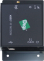
Coordinator

USB Cord

Power Cord

Antenna


Instructions
Replacement Installation
Select EXPAND to view an Animated Graphic for the step.
| Step 1: If your coordinator is powered, disconnect the Power from the outlet. |

|
| Step 2: Remove the antenna and disconnect the USB Cord from the Coordinator. If yours is powered, disconnect the power cord. |

|
| Step 3: Remove the old coordinator. Place new coordinator in the same place, attach the antenna and plug in the USB cord. |

|
| Step 4: Plug in the power cord to the coordinator. Plug in power to outlet. |

|
Step 5: Restart the VersaCall Service - Click here for Instructions
New Installation
1. Download the driver, you received from VersaCall Support - place the zip file on the VersaCall computer - unzip the file on the VersaCall computer.

2. Go to the location where the zip file was extracted - open the “CDM21224_Setup” folder – run the “CDM21224_Setup.exe” file.

3. Select Run on the first screen.

4. If you encounter a Windows Security screen about the installation, select Yes.
5. Select Extract on the FTDI CDM Drivers screen.

6. Select Next on the Installation Wizard screen.

7. Select Accept on the License Agreement screen - select Next.

8. Select Finish on the Completion screen.

9. Attach the Antenna to the Coordinator - screw onto threaded stud.

10. Plug in the USB cord to the input port on the Coordinator.

11. Plug in the Power Cord to the input port on the Coordinator.

12. Plug the Power Cord into an electrical outlet.

9. Plug the USB Cord from the Coordinator into an open USB port on the back of the VersaCall computer.

10. Open VT3000 web interface – log in – select Administration – select System Settings – select Service.


11. Select the Coordinators tab on the Service Settings page.
12. Select the Plus icon.

13. Coordinator Properties:

    a. Enabled – place a check mark in the box to enable the device.
    b. Network Name – enter a name for the coordinator.
    c. Driver – select USB Digi Mesh 900HP.
    d. Isolation Code – leave this set to 1 unless VersaCall instructs you to change it.
    e. Port – select the COM port labeled as Digi USB Serial Port.
14. Select Save & Exit.
15. Select Yes on the Restart warning message. This must be done to complete the setup.

16. Restart the VersaCall Service - Click here for Instructions.
Step by Step Guides
Install a Remote Coordinator on the Same Subnet as the VersaCall Control Unit
Install a Remote Coordinator on a Different Subnet from the VersaCall Control Unit
Change the System (ISO) Isolation Code
Having Trouble?

Submit a Service Ticket