VPIV - Create an Andon Table Panel
Andon Panel
An Andon Panel will show the state and duration of an alarm on any type of device. The state of the alarm can be used to create color changes in the cell. Our example is of a typical bingo board. The instructions below can be used for an Andon Panel or an Andon Widget.
Getting Started
1. Select the Andon Table Panel/Widget icon from the Add New list.
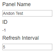
2. Enter a name for the panel in the Panel Name field under the Properties tab. Leave the Refresh Interval at 5.
Tags
1. Select the Tags tab - select to Add a tag.
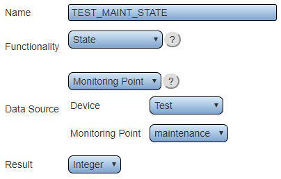
2. Create a State tag for each alarm on each device that needs to be shown on the panel/widget. For more information on creating a State tag Click Here.
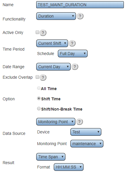
3. Create a Duration tag for each alarm on each device that needs to be shown on the panel/widget. For more information on creating a Duration tag Click Here
4. After all of the State and Duration tags are completed click on the Layout tab.
Layout
Headings
A panel needs to have a heading or title across the top and the alarm names running down the left side of the screen. This allows for easy understanding of the panel when viewed.
1. This panel will be for 4 modules with the same 4 alarms (Maintenance, Lead, Materials & Supervisor). Use the Rows & Column buttons to make 5 total columns and 6 total rows.
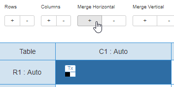
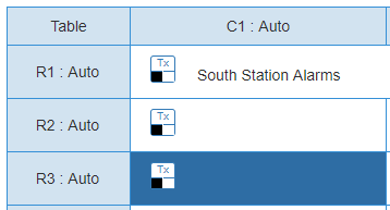
2. Select the R1 - C1 cell and use the Merge Horizontal (+) button to merge the top row. This will be our title/heading for the panel.
3. Use the Content field to enter the title/heading for the panel. Example below.
4. Select the R2 - C2 cell and use the Content field to enter the name of the first device that contains the 4 alarms. Repeat this for C3, C4 & C5. Example below.
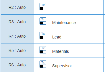
5. Select the R3 - C1 cell and use the Content field to enter the name of the first alarm "Maintenance".
6. Repeat the process for R4, R5 & R6 to enter the Lead, Materials & Supervisor headings.
Inactive Cell Setup
When there are no active calls for the cell it will be solid green.
1. Select the R3 - C2 cell.
2. Use the Type option at the bottom of the page and select Tag.
3. Select the the Maintenance Duration alarm for the appropriate station.
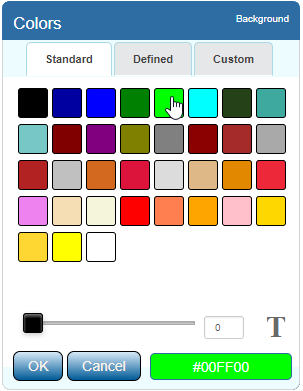
4. Select the Back color swatch - set the color to Green.
5. Select the Fore color swatch - set the color to Green.
6. Repeat the process for all remaining cells. Select the appropriate duration tag for the alarm matched to the device. Example below.
Conditions
Once a call is activated, the cell on the panel needs to change colors to indicate and issue. For the example, Red will indicate Active/Set and Yellow will indicate Acknowledged.
1. Select R3 - C2 cell.
2. Click on the Conditions button at the bottom of the page.
3. Select the Color tab.
4. Click on the Add Color Condition button.
5. In the Left Comparator field select the appropriate state tag for the alarm & device.
6. Select the (=) sign from the middle field.
7. Type 1 for the Right Comparator field.
8. Click on the Back color swatch - change the color to Red.
9. Click on the OK link when finished.
10. Click on the Add Color Condition button.
11. In the Left Comparator field select the appropriate state tag for the alarm & device.
12. Select the (=) sign from the middle field.
13. Type 2 for the Right Comparator field.
14. Click on the Back color swatch - change the color to Yellow.
15. Click on the OK link when finished.
16. Close the Conditions Window with the (X) button.
17. Repeat this process with all the remaining cells selecting the appropriate alarm/device state tag.
Final Step
After all of the tags are created, heading created and all the conditions have been setup the panel should look similar to the example below. Click on the Save & Exit button to save the panel.
NOTE: An Andon panel can have as many as 6 columns and 11 rows. This would provide the user with room to show 10 devices and 4 alarms each.

