VT3000 - Control/Use Attached Light Stack - BSC TIM PSM
Overview
This guide explains how to Control or Use the lights on the light stack that is attached/wired to BSC, TIM or PSM. The VersaCall system uses Actions to turn Outputs (lights for this guide) On, Off or Blink. This guide shows a typical setup for the lights where each alarm uses an output/light. If you have a need for something different, please go through the guide so that you get a good understanding of how things work then setup what makes sense for your needs.
There are 3 steps to the overall process:
Attach/Wire the Light Stack - Click here for Guide
Setup the Lights for the Module - Click here for Guide
Control the Lights for the Module - Covered in this Guide
Requirements
1. VT3000 Core Software installed and running on your system.
2. A Light Stack wired to a BSC, TIM or PSM.
3. The BSC, TIM or PSM with the stack light, powered and communicating with the system.
4. BSC, TIM or PSM configuration with the Lights setup as Outputs.
Instructions
1. Select a BSC, TIM or PSM configuration that you will be using an attached light stack with – select Edit.

2. Select the Monitoring Points tab.

3. Select the alarm, from the Root, that you want use a light with so that it is highlighted.

4. Select the Actions tab.

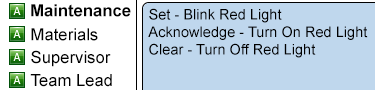
5. The Alarm we selected was setup as a Tri-State alarm. We will need to setup an Action for each State (Set, Acknowledged, Clear). The end result will look like the image below:

6. Select the Add icon from the Actions toolbar.

7. The Action Properties windows will show so that we can setup the Set behavior of the light.

    a. State – select Set.
    b. Type – select Modify Discrete Output.
    c. Action – select Blink.
    d. Output – select the output/light. We are using Red for this example.
8. Select the Add icon from the Actions toolbar.
9. The Action Properties window will show again so we can setup the Acknowledge behavior for the light.

    a. State – select Acknowledge.
    b. Type – select Modify Discrete Output.
    c. Action – select Turn On.
    d. Output – select the output/light. We are using Red for this example.
10. Select the Add icon from the Actions toolbar.
11. The Action Properties window will show again so we can setup the Clear behavior for the light.

    a. State – select Clear.
    b. Type – select Modify Discrete Output.
    c. Action – select Turn Off.
    d. Output – select the output/light. We are using Red for this example.
12. Repeat the steps for any other Alarms that you want to setup. The images below show the setup of 4 Alarms on a PSM where the Materials Alarm is Dual State and the others are Tri-State.
Tri-State


Dual State

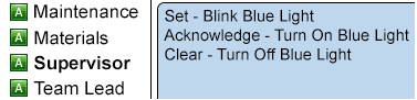
Tri-State

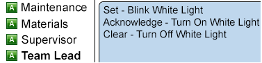
Tri-State

13. Select Save & Exit once you have setup all your Actions for each button.

Step by Step Guides
Attach & Wire a Stack Light to an Existing BSC, TIM or PSM
Setup the Outputs on a BSC, TIM or PSM to Coorespond with an Attached Light Stack
Having Trouble?

Submit a Service Ticket