VT3000 - Install Coordinator - Remote - Different Subnet
Revision as of 15:49, 3 September 2021 by SupportAdmin (talk | contribs)
Overview
This guide will show how to configure a remote coordinator that is on a different subnet than the VersaCall computer/server. For this method, you must have the IP address of the port that the RS232 device is plugged into – consult your IT department for this information. They may need to trace the device using the MAC address, this is printed on a label attached to the bottom of the RS-232 device. You will also need an IP address that you can use as a Static IP address for this device.
Unpack
You will have the following components after unpacking.

Coordinator

Power Cord

Antenna
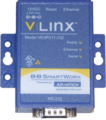
RS-232
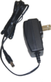
RS-232 Power

Serial Cable


Instructions
1. Connect the Serial Cable to the port on the Coordinator.

2. Connect the other end of the Serial Cable to the RS-232 device.

3. Connect the Power Cable to the Coordinator.

4. Connect the Antenna to the Coordinator.

5. Connect the Power Cable to the RS-232 device.

6. Connect the Ethernet Cable to the RS-232 device.

7. Connect the Ethernet Cable to your available port.

8. Connect both Power Cables to an Electrical Outlet.

9. Open a web browser - type in the IP address for the port the RS232 device in plugged into.

NOTE If you do not have the IP address have your IT department perform a MAC address search for the RS-232 device. The MAC address is printed on the back of the RS-232 device.
10. Leave the Password field blank – select the Login button.

11. Enter any name to identify the Coordinator – select the Next button.

12. Enter the IP Address information provided by your IT department – select the Next button.

13. Use the Settings below:

    a. Network Protocol – select TCP – select “to wait for connections”.
    b. Port Number – enter 4000 for the Port number unless told otherwise by IT.
    c. Limit – select 4 connections from the drop down list.
    d. IP Address – enter the IP address of the VersaCall computer. If you do not know the IP address, please contact IT for further assistance.
NOTE: The IP address shown in the image is just for reference purposes – only use the IP address of your VersaCall computer.
14. Select the Advanced button.
![]()
15. Use the Settings below:

    a.	Advanced – click in the box next to “I want to control when connections would be forced to close” to place a check mark in it.
    b.	Network – click in the box next to “I want to close a connection” to place a check mark in it.
            i.	Select “after the connection ……” and enter 2 in the field for minutes.
    c.	Serial – uncheck the box and leave the milliseconds field blank.
    d.	Data Packets – do not select the option to control data packets.
16. Select the Next button.

17. Use the Settings below:

    a.	Description – enter Serial Port 1
    b.	Mode – select RS-232
    c.	Baud Rate – select 115200
    d.	Data Bits – select 8-Bits
    e.	Stop Bits – select 1-Bit
    f.	Parity – select No Parity
    g.	Flow Control – select Hardware (RTS/CTS)
18. Select the Next button.

19. Select the Save button.

20. Open the VT3000 home page – select VT3000 - log in – select Administration – System Settings – Service.


21. Select the add or “+” icon.

22. Use the Settings below:

    a.	Enabled – click on the box to place a check mark – this will enable the device.
    b.	Network Name – enter any name that you wish. This name will show on the Device Status page.
    c.	Driver – select the Remote DigiMesh 900HP driver from the list.
    d.	Isolation Code – if this is the only coordinator, leave the number as 1. If this is an additional coordinator select 2.
    e.	Connection Method – select TCP Client from the list.
    f.	Address – enter the IP address for the device (one entered in step 12).
    g.	Port – enter 4000.
23. Select the Save & Exit button.

24. Select Yes on the Restart warning message. This must be done to complete the setup.

25. Restart the VersaCall Service - Click here for Instructions.
26. From the Home screen select Diagnostics – Device Status.


27. The Coordinator will show as red - communications take 30 seconds to 1 minute to establish.

28. After the refresh the Coordinator will show as black - communication has been established.

|
| |||||||