Difference between revisions of "VT3000 Devices"
Jump to navigation
Jump to search

SupportAdmin (talk | contribs) (Created page with "Under Constructions") |
SupportAdmin (talk | contribs) |
||
| (25 intermediate revisions by the same user not shown) | |||
| Line 1: | Line 1: | ||
{|style="background:transparent; color:black" border="0" height="230" align="center" valign="bottom" | |||
|+style="background:transparent| | |||
|-align="center" | |||
| | |||
|[[Image:CallUsBtn.png|Call Now 858-677-6766]] | |||
| | |||
|[[Image:SubmitTckBtn.png|link=https://www.versacall.com/customer-support/service-ticket]] | |||
| | |||
|[[Image:EmailUsBtn.png|link=mailto:[email protected]?Subject=Help%20Needed%20Wiki&body=Type%20Message%20Here]] | |||
|} | |||
<BR> | |||
<div style="box-shadow: 0 0 10px 0 #b1d5ee inset; border-radius:5px; padding:10px; padding-left:20px; background:#ebf4fa;"> | |||
<span style="color:#00719e; font-family: Helvetica; font-size:150%; font-variant: small-caps; padding-left:20px;">'''Detailed Information'''</span> | |||
:*Each device has a specific duty in the VT3000 system. | |||
:*To accomplish the task, each module has a specific set of monitoring points, outputs and inputs that can be created/added to it. | |||
:*Each of the icons shown below also show in the Add list when adding a device. | |||
{|style="margin:left; padding:20px;" | |||
|valign="top" | | |||
{|class="wikitable" style="background:white; align:center; width:775px; border:2px solid #000000;" | |||
|- | |||
| || [[File:CS Icon.png|center|40px]] || [[File:BSC Icon.png|center|40px]] || [[File:TIM Icon.png|center|58px]] || [[File:PSM Icon.png|center|58px]] | |||
|- | |||
| || style="text-align:center" | '''Call Station''' || style="text-align:center" | '''BSC''' || style="text-align:center" | '''TIM''' || style="text-align:center" | '''PSM''' | |||
|- | |||
|style="width: 20%; background-color:#F0F0F0; text-align:center" | '''Alarm''' || style="text-align:center; background-color:#F0F0F0;" | <big>'''X'''</big> || style="text-align:center; background-color:#F0F0F0;" | <big>'''X'''</big> || style="text-align:center; background-color:#F0F0F0;" | <big>'''X'''</big> || style="text-align:center; background-color:#F0F0F0;" | <big>'''X'''</big> | |||
|- | |||
|style="width: 20%; text-align:center" | '''Data Field''' || || style="text-align:center" | <big>'''X'''</big> || style="text-align:center" | <big>'''X'''</big> || style="text-align:center" | <big>'''X'''</big> | |||
|- | |||
|style="width: 20%; background-color:#F0F0F0; text-align:center" | '''Process''' || style="text-align:center; background-color:#F0F0F0;"| || style="text-align:center; background-color:#F0F0F0; " | <big>'''X'''</big> || style="text-align:center; background-color:#F0F0F0;" | <big>'''X'''</big> || style="text-align:center; background-color:#F0F0F0;" | <big>'''X'''</big> | |||
|- | |||
|style="width: 20%; text-align:center" | '''Sampler/Count''' || || style="text-align:center" | <big>'''X'''</big> || style="text-align:center" | <big>'''X'''</big> || style="text-align:center" | <big>'''X'''</big> | |||
|- | |||
|style="width: 20%; background-color:#F0F0F0; text-align:center" | '''Output''' || style="text-align:center; background-color:#F0F0F0;" | <big>'''X'''</big> || style="text-align:center; background-color:#F0F0F0;" | <big>'''X'''</big> || style="text-align:center; background-color:#F0F0F0;" | <big>'''X'''</big> || style="text-align:center; background-color:#F0F0F0;" | <big>'''X'''</big> | |||
|- | |||
|style="width: 20%; text-align:center" | '''Input''' || || || style="text-align:center" | <big>'''X'''</big> || style="text-align:center" | <big>'''X'''</big> | |||
|- | |||
|style="width: 20%; background-color:#F0F0F0; text-align:center" | '''Virtual Input''' || style="text-align:center; background-color:#F0F0F0;" | || style="text-align:center; background-color:#F0F0F0;" | || style="text-align:center; background-color:#F0F0F0;" | <big>'''X'''</big> || style="text-align:center; background-color:#F0F0F0;" | <big>'''X'''</big> | |||
|- | |||
|style="width: 20%; text-align:center" | '''Indicators''' || || || || style="text-align:center" | <big>'''X'''</big> | |||
|} | |||
{|class="wikitable" style="background:white; align:center; width:775px; border:2px solid #000000;" | |||
|- | |||
| || [[File:Takt Icon.png|center|40px]] || [[File:Takt Icon.png|center|40px]] || colspan="3" | [[File:IO Icon.png|center|54px]] | |||
|- | |||
| || style="text-align:center" | '''Assy. Call Station''' || style="text-align:center" | '''Takt Module''' || style="text-align:center" | '''Wireless Audio''' || style="text-align:center" | '''Wireless Light''' || style="text-align:center" | '''Switch Contact''' | |||
|- | |||
|style="width: 20%; text-align:center" | '''Alarm''' || style="text-align:center" | <big>'''X'''</big> || style="text-align:center" | <big>'''X'''</big> || || || style="text-align:center" | <big>'''X'''</big> | |||
|- | |||
|style="width: 20%; text-align:center" | '''Sampler/Count''' || || || || || style="text-align:center" | <big>'''X'''</big> | |||
|- | |||
|style="width: 20%; text-align:center" | '''Output''' || style="text-align:center" | <big>'''X'''</big> || style="text-align:center" | <big>'''X'''</big> || style="text-align:center" | <big>'''X'''</big> || style="text-align:center" | <big>'''X'''</big> || style="text-align:center" | <big>'''X'''</big> | |||
|- | |||
|style="width: 20%; text-align:center" | '''Input''' || || || || || style="text-align:center" | <big>'''X'''</big> | |||
|} | |||
{|class="wikitable" style="background:white; align:center; width:775px; border:2px solid #000000;" | |||
|- | |||
|style="text-align:center" colspan="4" |<big>'''PC Devices'''</big> | |||
|- | |||
| || [[File:PCCS Icon.png|center|39px]] || [[File:PCBSC Icon.png|center|40px]] || [[File:PCIn Icon.png|center|48px]] | |||
|- | |||
| || style="text-align:center" | '''PC Call Station''' || style="text-align:center" | '''PC BSC''' || style="text-align:center" | '''PC Input Module''' | |||
|- | |||
|style="width: 20%; text-align:center" | '''Alarm''' || style="text-align:center" | <big>'''X'''</big> || style="text-align:center" | <big>'''X'''</big> || style="text-align:center" | <big>'''X'''</big> | |||
|- | |||
|style="width: 20%; text-align:center" | '''Data Field''' || || style="text-align:center" | <big>'''X'''</big> || style="text-align:center" | <big>'''X'''</big> | |||
|- | |||
|style="width: 20%; text-align:center" | '''Process''' || || style="text-align:center" | <big>'''X'''</big> || style="text-align:center" | <big>'''X'''</big> | |||
|- | |||
|style="width: 20%; text-align:center" | '''Sampler/Count''' || || style="text-align:center" | <big>'''X'''</big> || style="text-align:center" | <big>'''X'''</big> | |||
|- | |||
|style="width: 20%; text-align:center" | '''Virtual Input''' || || || style="text-align:center" | <big>'''X'''</big> | |||
|} | |||
|} | |||
</div> | |||
<BR> | |||
<div style="box-shadow: 0 0 10px 0 #b1d5ee inset; border-radius:5px; padding:10px; padding-left:20px; background:#ebf4fa;"> | |||
<span style="color:#00719e; font-family: Helvetica; font-size:150%; font-variant: small-caps; padding-left:20px;">'''Basic Functionality'''</span> | |||
:<span style="color:#90A4AE; font-size:130%">'''Add Device Configuration''' - Select the Icon of the type of Device you want to Add.</span> | |||
<gallery widths=349px heights=464px> | |||
Image:Add Device.png|link=VT3000 Devices | |||
</gallery> | |||
<BR> | |||
:<span style="color:#90A4AE; font-size:130%">'''Edit Device Configuration''' - Select an existing Device Configuration from the list. Select the '''Edit''' button.</span> | |||
<gallery widths=353px heights=402px> | |||
Image:Edit Device.png|link=VT3000 Devices | |||
</gallery> | |||
<BR> | |||
:<span style="color:#90A4AE; font-size:130%">'''Remove Device Configuration''' - Select an existing Device Configuration from the list. Select the '''Delete''' button.</span> | |||
<gallery widths=352px heights=403px> | |||
Image:Delete Device.png|link=VT3000 Devices | |||
</gallery> | |||
<BR> | |||
:<span style="color:#90A4AE; font-size:130%">'''Copy Device Configuration''' - Select an existing Device Configuration from the list. Select the '''Copy''' button.</span> | |||
<gallery widths=353px heights=402px> | |||
Image:Copy Device.png|link=VT3000 Devices | |||
</gallery> | |||
</div> | |||
<BR> | |||
<div style="box-shadow: 0 0 10px 0 #b1d5ee inset; border-radius:5px; padding:10px; padding-left:20px; background:#ebf4fa;"> | |||
<span style="color:#00719e; font-family: Helvetica; font-size:150%; font-variant: small-caps; padding-left:20px;">'''Device Properties'''</span> | |||
:*When a device is added, edited or copied the Properties tab is the first tab shown on all device types. | |||
:*Use this section to enter a name for the device. | |||
<gallery widths=300px heights=49px> | |||
Image:Prop2Tab.png|link=VT3000 Devices | |||
</gallery> | |||
<gallery widths=518px heights=98px> | |||
Image:PropName2.png|link=VT3000 Devices | |||
</gallery> | |||
</div> | |||
<BR> | |||
<div style="box-shadow: 0 0 10px 0 #b1d5ee inset; border-radius:5px; padding:10px; padding-left:20px; background:#ebf4fa;"> | |||
<span style="color:#00719e; font-family: Helvetica; font-size:150%; font-variant: small-caps; padding-left:20px;">'''Monitoring Points'''</span> | |||
:*After selecting the Monitoring Points tab, there will be up to 4 monitoring points available to be added. | |||
:*The number of Monitoring Points shown will depend on the Device Type selected. | |||
<gallery widths=100px perrow="4"> | |||
Image:Process Icon.png|<div style="text-align: center; color:#90A4AE">'''Process'''</div>|link=VT3000 Process | |||
Image:Alarm Icon.png|<div style="text-align: center; color:#90A4AE">'''Alarm'''</div>|link=VT3000 Alarm | |||
Image:Data Icon.png|<div style="text-align: center; color:#90A4AE">'''Data Field'''</div>|link=VT3000 Data Field | |||
Image:Sampler Icon.png|<div style="text-align: center; color:#90A4AE">'''Sampler'''</div>|link=Sampler Icon.png | |||
</gallery> | |||
</div> | |||
<BR> | |||
<div style="box-shadow: 0 0 10px 0 #b1d5ee inset; border-radius:5px; padding:10px; padding-left:20px; background:#ebf4fa;"> | |||
<span style="color:#00719e; font-family: Helvetica; font-size:150%; font-variant: small-caps; padding-left:20px;">'''Discrete Outputs'''</span> | |||
:*Outputs After selecting the Discrete Outputs tab, there will be 7 outputs available. | |||
:*Select an Output to set it up. | |||
<gallery widths=185px heights=200> | |||
Image:Output Setup.png|<div style="text-align: center; color:#90A4AE">'''Output Setup'''</div>|link=VT3000 Discrete Outputs | |||
</gallery> | |||
</div> | |||
<BR> | |||
<div style="box-shadow: 0 0 10px 0 #b1d5ee inset; border-radius:5px; padding:10px; padding-left:20px; background:#ebf4fa;"> | |||
<span style="color:#00719e; font-family: Helvetica; font-size:150%; font-variant: small-caps; padding-left:20px;">'''Discrete Inputs'''</span> | |||
:*After selecting the Discrete Inputs tab, there will be 4 inputs available. | |||
:*Select an Input to set it up. | |||
<gallery widths=149px heights=113> | |||
Image:Input Setup.png|<div style="text-align: center; color:#90A4AE">'''Input Setup'''</div>|link=VT3000 Discrete Inputs | |||
</gallery> | |||
</div> | |||
<BR> | |||
<div style="box-shadow: 0 0 10px 0 #b1d5ee inset; border-radius:5px; padding:10px; padding-left:20px; background:#ebf4fa;"> | |||
<span style="color:#00719e; font-family: Helvetica; font-size:150%; font-variant: small-caps; padding-left:20px;">'''Indicators'''</span> | |||
:*After selecting the Indicators tab, select the Add icon or an Indicator. | |||
:*Either selection will allow you to access the Indicator Properties. | |||
<gallery widths=142px heights=176> | |||
Image:Indicator.png|<div style="text-align: center; color:#90A4AE">'''Indicator Setup'''</div>|link=VT3000 Indicators | |||
</gallery> | |||
</div> | |||
<BR> | |||
<div style="box-shadow: 0 0 10px 0 #b1d5ee inset; border-radius:5px; padding:10px; padding-left:20px; background:#ebf4fa;"> | |||
<span style="color:#00719e; font-family: Helvetica; font-size:150%; font-variant: small-caps; padding-left:20px;">'''Virtual Inputs'''</span> | |||
:*After selecting the Virtual Inputs tab, select the Add icon or an existing Input. | |||
:*Either selection will allow you to access the Virtual Input Properties. | |||
<gallery widths=166px heights=171> | |||
Image:VInput.png|<div style="text-align: center; color:#90A4AE">'''Virtual Input Setup'''</div>|link=VT3000 Virtual Inputs | |||
</gallery> | |||
</div> | |||
<BR> | |||
<div style="box-shadow: 0 0 10px 0 #b1d5ee inset; border-radius:5px; padding:10px; padding-left:20px; background:#ebf4fa;"> | |||
<span style="color:#00719e; font-family: Helvetica; font-size:150%; font-variant: small-caps; padding-left:20px;">'''Communications'''</span> | |||
:*After setting up an Alarm, the Communications tab will be available in the Alarm Properties. | |||
:*Select the Communications tab to access the communication path(s) setup & properties. | |||
<gallery widths=203px heights=45> | |||
Image:Comm Tab.png|<div style="text-align: center; color:#90A4AE">'''Communications Setup'''</div>|link=VT3000 Communications | |||
</gallery> | |||
</div> | |||
<BR> | |||
<div style="box-shadow: 0 0 10px 0 #b1d5ee inset; border-radius:5px; padding:10px; padding-left:20px; background:#ebf4fa;"> | |||
<span style="color:#00719e; font-family: Helvetica; font-size:150%; font-variant: small-caps; padding-left:20px;">'''Actions'''</span> | |||
:*After setting up a monitoring point, the Actions tab will be available in the Alarm Properties. | |||
:*Select the Actions tab to access the Actions setup & properties. | |||
<gallery widths=120px heights=47> | |||
Image:Action Tab.png|<div style="text-align: center; color:#90A4AE">'''Actions Setup'''</div>|link=VT3000 Communications | |||
</gallery> | |||
</div> | |||
<BR> | |||
<div style="box-shadow: 0 0 10px 0 #b1d5ee inset; border-radius:5px; padding:10px; padding-left:20px; background:#ebf4fa;"> | |||
<span style="color:#00719e; font-family: Helvetica; font-size:150%; font-variant: small-caps; padding-left:10px;">'''Keyword Search'''</span> | |||
{|style="margin:auto;" | |||
{|class="wikitable" style="align:center; width:600px;" | |||
|- | |||
!<span style="color:#0054a6; font-size:120%"><big>Type Subject or Key Word to Query Archives</big></span> | |||
|- | |||
|<inputbox>type=search</inputbox> | |||
|} | |||
|} | |||
</div> | |||
<br> | |||
[[File:VC Footer.png|center|link=Main Page]] | |||
{|style="background:transparent; color:black" border="0" height="200" align="center" valign="bottom" cellpadding=10px cellspacing=10px | |||
|+style="background:transparent| | |||
|-align="center" | |||
| | |||
|[[File:LinkedIn.png|Follow Us On LinkedIn|link=https://www.linkedin.com/company/versacall/]] | |||
| | |||
|[[File:BlogIcon.png|View our Blog|link=https://www.versacall.com/blog/]] | |||
|} | |||
Latest revision as of 14:45, 21 November 2023

|

|

|
Detailed Information
- Each device has a specific duty in the VT3000 system.
- To accomplish the task, each module has a specific set of monitoring points, outputs and inputs that can be created/added to it.
- Each of the icons shown below also show in the Add list when adding a device.
| ||||||||||||||||||||||||||||||||||||||||||||||||||||||||||||||||||||||||||||||||||||||||||||||||||||||||||||||||||||||
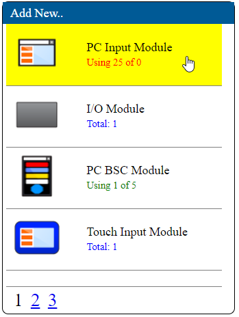
Basic Functionality
- Add Device Configuration - Select the Icon of the type of Device you want to Add.
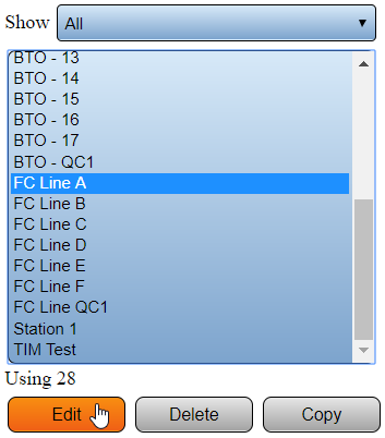
- Edit Device Configuration - Select an existing Device Configuration from the list. Select the Edit button.
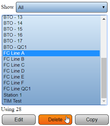
- Remove Device Configuration - Select an existing Device Configuration from the list. Select the Delete button.
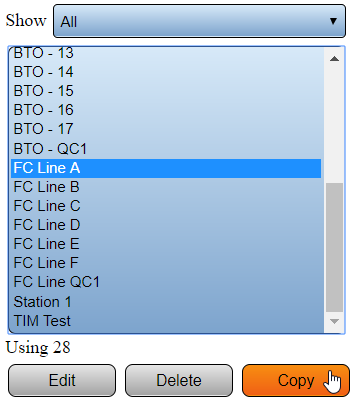
- Copy Device Configuration - Select an existing Device Configuration from the list. Select the Copy button.
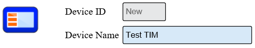
Device Properties
- When a device is added, edited or copied the Properties tab is the first tab shown on all device types.
- Use this section to enter a name for the device.
Monitoring Points
- After selecting the Monitoring Points tab, there will be up to 4 monitoring points available to be added.
- The number of Monitoring Points shown will depend on the Device Type selected.
 Process
 Alarm
Alarm Data Field
 Sampler
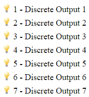
Discrete Outputs
- Outputs After selecting the Discrete Outputs tab, there will be 7 outputs available.
- Select an Output to set it up.
 Output Setup
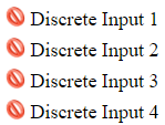
Discrete Inputs
- After selecting the Discrete Inputs tab, there will be 4 inputs available.
- Select an Input to set it up.
 Input Setup
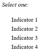
Indicators
- After selecting the Indicators tab, select the Add icon or an Indicator.
- Either selection will allow you to access the Indicator Properties.
 Indicator Setup
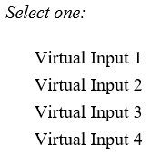
Virtual Inputs
- After selecting the Virtual Inputs tab, select the Add icon or an existing Input.
- Either selection will allow you to access the Virtual Input Properties.
 Virtual Input Setup
Communications
- After setting up an Alarm, the Communications tab will be available in the Alarm Properties.
- Select the Communications tab to access the communication path(s) setup & properties.
 Communications Setup
Actions
- After setting up a monitoring point, the Actions tab will be available in the Alarm Properties.
- Select the Actions tab to access the Actions setup & properties.
 Actions Setup
Keyword Search
| Type Subject or Key Word to Query Archives |
|---|

|