Difference between revisions of "VT3000 - Control/Use Attached Light Stack - BSC TIM PSM"
Jump to navigation
Jump to search
SupportAdmin (talk | contribs) (Created page with "=Overview= This guide explains how to Control or Use the lights on the light stack that is attached/wired to BSC, TIM or PSM. The VersaCall system uses Actions to turn Outputs...") |
SupportAdmin (talk | contribs) |
||
| (12 intermediate revisions by the same user not shown) | |||
| Line 1: | Line 1: | ||
= | {|style="background:transparent; color:black" border="0" height="230" align="center" valign="bottom" | ||
|+style="background:transparent| | |||
|-align="center" | |||
| | |||
|[[Image:CallUsBtn.png|Call Now 858-677-6766]] | |||
| | |||
|[[Image:SubmitTckBtn.png|link=https://www.versacall.com/customer-support/service-ticket]] | |||
| | |||
|[[Image:EmailUsBtn.png|link=mailto:[email protected]?Subject=Help%20Needed%20Wiki&body=Type%20Message%20Here]] | |||
|} | |||
<br> | |||
---- | |||
= | ---- | ||
<br> | |||
''' | [[File:GeneralHeader.png]] | ||
<br> | |||
{|style="margin:left; width: 100px; background:#eaf3ff; padding:5px; border:2px solid #000000;" | |||
|- | |||
|<big>'''Overview'''</big> | |||
{|style="margin:left; width: 800px; background:#F0F0F0; padding:5px; border:2px solid #000000;" | |||
|valign="top" | | |||
|- | |||
|This guide explains how to Control or Use the lights on the light stack that is attached/wired to BSC, TIM or PSM. The VersaCall system uses Actions to turn Outputs (lights for this guide) On, Off or Blink. This guide shows a typical setup for the lights where each alarm uses an output/light. If you have a need for something different, please go through the guide so that you get a good understanding of how things work then setup what makes sense for your needs. | |||
|} | |||
= | |} | ||
<br> | |||
''' | {|style="margin:left; width: 100px; background:#eaf3ff; padding:5px; border:2px solid #000000;" | ||
|- | |||
|<big>'''Requirements'''</big> | |||
{|style="margin:left; width: 800px; background:#F0F0F0; padding:5px; border:2px solid #000000;" | |||
|valign="top" | | |||
{| class="wikitable mw-collapsible mw-collapsed" width="775px;" | |||
|- | |||
''' | |style="text-align: center;" | '''See Requirements Here''' | ||
|- | |||
|'''1.''' The VT3000 Core Software installed and running on your system. | |||
|- | |||
|'''2.''' A Coordinator must be setup, powered and communicating with the VT3000 Core Software. | |||
|- | |||
|'''3.''' A BSC, TIM or PSM IO Module, with an attached Light Stack, powered and communicating with the VT3000 Software. | |||
''' | |- | ||
|'''4.''' An existing BSC, TIM or PSM configuration with Lights setup as Outputs. | |||
|} | |||
|} | |||
|} | |||
<br> | |||
{|style="margin:left; width: 100px; background:#eaf3ff; padding:5px; border:2px solid #000000;" | |||
''' | |- | ||
|<big>'''Completion Steps'''</big> | |||
{|style="margin:left; width: 800px; background:#F0F0F0; padding:5px; border:2px solid #000000;" | |||
|valign="top" | | |||
|- | |||
|[[File:LightPart1.png|258 px|link=VT3000 - Attach/Wire a Light Stack to a BSC TIM PSM]] ||[[File:LightPart2.png|258 px|link=VT3000 - Setup Attached Light Stack - BSC TIM PSM]] || [[File:LightPart3A.png|258 px|link=VT3000 - Control/Use Attached Light Stack - BSC TIM PSM]] | |||
|} | |||
''' | |} | ||
<br> | |||
---- | |||
File: | ---- | ||
<br> | |||
[[File:InstructionHeader.png]] | |||
<br> | |||
{|style="margin:left; width: 100px; background:#eaf3ff; padding:5px; border:2px solid #000000;" | |||
|- | |||
|<big>'''Step 1.'''</big> | |||
{|style="margin:left; width: 800px; background:#F0F0F0; padding:5px; border:2px solid #000000;" | |||
|valign="top" | | |||
|- | |||
|Open the VT3000 web interface – select VT3000 Core Software - log in – select Configuration – select Devices. | |||
{|style="margin:left;" | |||
|valign="top" | | |||
< | {|class="wikitable" style="background:white; align:center;" | ||
File: | |- | ||
< | |[[File:3137_1.png|center|93px]] || [[File:3137_2.png|center|93px]] | ||
|- | |||
|style="text-align:center" | '''Configuration''' ||style="text-align:center" | '''Devices''' | |||
|} | |||
|} | |||
|} | |||
|} | |||
<br> | |||
---- | |||
<br> | |||
{|style="margin:left; width: 100px; background:#eaf3ff; padding:5px; border:2px solid #000000;" | |||
File: | |- | ||
|<big>'''Step 2.'''</big> | |||
{|style="margin:left; width: 800px; background:#F0F0F0; padding:5px; border:2px solid #000000;" | |||
|valign="top" | | |||
''' | |- | ||
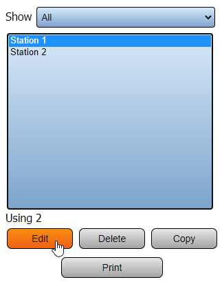
|Select the Configuration of the BSC, TIM or PSM with the Light Stack attached from the list – select Edit. | |||
{|style="margin:left;" | |||
|valign="top" | | |||
< | {|class="wikitable" style="background:white; align:center;" | ||
|- | |||
|[[File:PSMLts1.png|center|323px]] | |||
|} | |||
|} | |||
|} | |||
|} | |||
<br> | |||
---- | |||
<br> | |||
{|style="margin:left; width: 100px; background:#eaf3ff; padding:5px; border:2px solid #000000;" | |||
|- | |||
< | |<big>'''Step 3.'''</big> | ||
{|style="margin:left; width: 800px; background:#F0F0F0; padding:5px; border:2px solid #000000;" | |||
|valign="top" | | |||
''' | |- | ||
|Select the Monitoring Points tab. | |||
{|style="margin:left;" | |||
|valign="top" | | |||
{|class="wikitable" style="background:white; align:center;" | |||
|- | |||
|[[File:3137 16.png|center|452px]] | |||
|} | |||
|} | |||
|} | |||
|} | |||
<br> | |||
---- | |||
<br> | |||
{|style="margin:left; width: 100px; background:#eaf3ff; padding:5px; border:2px solid #000000;" | |||
|- | |||
|<big>'''Step 4.'''</big> | |||
{|style="margin:left; width: 800px; background:#F0F0F0; padding:5px; border:2px solid #000000;" | |||
File: | |valign="top" | | ||
|- | |||
|Select the alarm, from the Root, that you want use a light with so that it is highlighted. | |||
{|style="margin:left;" | |||
< | |valign="top" | | ||
< | {|class="wikitable" style="background:white; align:center;" | ||
|- | |||
< | |[[File:CallLts8.png|center|141px]] | ||
|} | |||
|} | |||
''' | |} | ||
|} | |||
<br> | |||
File: | ---- | ||
<br> | |||
{|style="margin:left; width: 100px; background:#eaf3ff; padding:5px; border:2px solid #000000;" | |||
|- | |||
|<big>'''Step 5.'''</big> | |||
{|style="margin:left; width: 800px; background:#F0F0F0; padding:5px; border:2px solid #000000;" | |||
|valign="top" | | |||
|- | |||
|Select the Actions tab. | |||
{|style="margin:left;" | |||
= | |valign="top" | | ||
{|class="wikitable" style="background:white; align:center;" | |||
< | |- | ||
|[[File:3137 19.png|center|364px]] | |||
|} | |||
|} | |||
|} | |||
|} | |||
<br> | |||
---- | |||
<br> | |||
{|style="margin:left; width: 100px; background:#eaf3ff; padding:5px; border:2px solid #000000;" | |||
|- | |||
|<big>'''Step 6.'''</big> | |||
{|style="margin:left; width: 800px; background:#F0F0F0; padding:5px; border:2px solid #000000;" | |||
|valign="top" | | |||
|- | |||
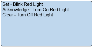
|The Alarm we selected was setup as a Tri-State alarm. We will need to setup an Action for each State (Set, Acknowledged, Clear). The end result will look like the image below: | |||
{|style="margin:left;" | |||
|valign="top" | | |||
{|class="wikitable" style="background:white; align:center;" | |||
|- | |||
|[[File:3137 20.png|center|307px]] | |||
|} | |||
|} | |||
|} | |||
|} | |||
<br> | |||
---- | |||
<br> | |||
{|style="margin:left; width: 100px; background:#eaf3ff; padding:5px; border:2px solid #000000;" | |||
|- | |||
|<big>'''Step 7.'''</big> | |||
{|style="margin:left; width: 800px; background:#F0F0F0; padding:5px; border:2px solid #000000;" | |||
|valign="top" | | |||
|- | |||
|Select the Add icon from the Actions toolbar. | |||
{|style="margin:left;" | |||
|valign="top" | | |||
{|class="wikitable" style="background:white; align:center;" | |||
|- | |||
|[[File:CallLts1.png|center|263px]] | |||
|} | |||
|} | |||
|} | |||
|} | |||
<br> | |||
---- | |||
<br> | |||
{|style="margin:left; width: 100px; background:#eaf3ff; padding:5px; border:2px solid #000000;" | |||
|- | |||
|<big>'''Step 8.'''</big> | |||
{|style="margin:left; width: 800px; background:#F0F0F0; padding:5px; border:2px solid #000000;" | |||
|valign="top" | | |||
|- | |||
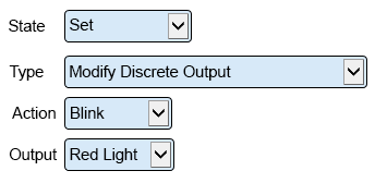
|Action Properties that need to be setup for the Set state of the alarm: | |||
{|style="margin:left;" | |||
|valign="top" | | |||
{|class="wikitable" style="background:white; align:center; width:775px;" | |||
|- | |||
|[[File:3137 21.png|center|344px]] | |||
|} | |||
{|class="wikitable" style="background:white; align:center; width:775px;" | |||
|- | |||
|'''State''' – select Set. | |||
|- | |||
|'''Type''' – select Modify Discrete Output. | |||
|- | |||
|'''Action''' – select Blink. | |||
|- | |||
|'''Output''' – select the output/light. We are using Red for this example. | |||
|} | |||
|} | |||
|} | |||
|} | |||
<br> | |||
---- | |||
<br> | |||
{|style="margin:left; width: 100px; background:#eaf3ff; padding:5px; border:2px solid #000000;" | |||
|- | |||
|<big>'''Step 9.'''</big> | |||
{|style="margin:left; width: 800px; background:#F0F0F0; padding:5px; border:2px solid #000000;" | |||
|valign="top" | | |||
|- | |||
|Select the Add icon from the Actions toolbar. | |||
{|style="margin:left;" | |||
|valign="top" | | |||
{|class="wikitable" style="background:white; align:center;" | |||
|- | |||
|[[File:CallLts1.png|center|263px]] | |||
|} | |||
|} | |||
|} | |||
|} | |||
<br> | |||
---- | |||
<br> | |||
{|style="margin:left; width: 100px; background:#eaf3ff; padding:5px; border:2px solid #000000;" | |||
|- | |||
|<big>'''Step 10.'''</big> | |||
{|style="margin:left; width: 800px; background:#F0F0F0; padding:5px; border:2px solid #000000;" | |||
|valign="top" | | |||
|- | |||
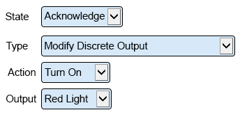
|Action Properties that need to be setup for the Acknowledge state of the alarm. If you are setting up a Dual State alarm skip to the next step: | |||
{|style="margin:left;" | |||
|valign="top" | | |||
{|class="wikitable" style="background:white; align:center; width:775px;" | |||
|- | |||
|[[File:CallLts2.png|center|344px]] | |||
|} | |||
{|class="wikitable" style="background:white; align:center; width:775px;" | |||
|- | |||
|'''State''' – select Acknowledge. | |||
|- | |||
|'''Type''' – select Modify Discrete Output. | |||
|- | |||
|'''Action''' – select Turn On. | |||
|- | |||
|'''Output''' – select the output/light. We are using Red for this example. | |||
|} | |||
|} | |||
|} | |||
|} | |||
<br> | |||
---- | |||
<br> | |||
{|style="margin:left; width: 100px; background:#eaf3ff; padding:5px; border:2px solid #000000;" | |||
|- | |||
|<big>'''Step 11.'''</big> | |||
{|style="margin:left; width: 800px; background:#F0F0F0; padding:5px; border:2px solid #000000;" | |||
|valign="top" | | |||
|- | |||
|Select the Add icon from the Actions toolbar. | |||
{|style="margin:left;" | |||
|valign="top" | | |||
{|class="wikitable" style="background:white; align:center;" | |||
|- | |||
|[[File:CallLts1.png|center|263px]] | |||
|} | |||
|} | |||
|} | |||
|} | |||
<br> | |||
---- | |||
<br> | |||
{|style="margin:left; width: 100px; background:#eaf3ff; padding:5px; border:2px solid #000000;" | |||
|- | |||
|<big>'''Step 12.'''</big> | |||
{|style="margin:left; width: 800px; background:#F0F0F0; padding:5px; border:2px solid #000000;" | |||
|valign="top" | | |||
|- | |||
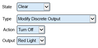
|Action Properties that need to be setup for the Clear state of the alarm. | |||
{|style="margin:left;" | |||
|valign="top" | | |||
{|class="wikitable" style="background:white; align:center; width:775px;" | |||
|- | |||
|[[File:CallLts3.png|center|344px]] | |||
|} | |||
{|class="wikitable" style="background:white; align:center; width:775px;" | |||
|- | |||
|'''State''' – select Clear. | |||
|- | |||
|'''Type''' – select Modify Discrete Output. | |||
|- | |||
|'''Action''' – select Turn Off. | |||
|- | |||
|'''Output''' – select the output/light. We are using Red for this example. | |||
|} | |||
|} | |||
|} | |||
|} | |||
<br> | |||
---- | |||
<br> | |||
{|style="margin:left; width: 100px; background:#eaf3ff; padding:5px; border:2px solid #000000;" | |||
|- | |||
|<big>'''Step 13.'''</big> | |||
{|style="margin:left; width: 800px; background:#F0F0F0; padding:5px; border:2px solid #000000;" | |||
|valign="top" | | |||
|- | |||
|Repeat the steps for any other Alarms that you want to setup. The images below show the setup of 4 Alarms on a device where one alarm is Dual State and the others are Tri-State. | |||
{|style="margin:left;" | |||
|valign="top" | | |||
{|class="wikitable" style="background:white; align:center; width:775px;" | |||
|- | |||
|[[File:CallLts9.png|center|377px]] || [[File:CallLts10.png|center|377px]] | |||
|- | |||
|style="text-align:center" | '''Tri-State''' ||style="text-align:center" | '''Dual State''' | |||
|} | |||
{|class="wikitable" style="background:white; align:center; width:775px;" | |||
|- | |||
|[[File:CallLts11.png|center|377px]] || [[File:CallLts12.png|center|377px]] | |||
|- | |||
|style="text-align:center" | '''Tri-State''' ||style="text-align:center" | '''Tri-State''' | |||
|} | |||
|} | |||
|} | |||
|} | |||
<br> | |||
---- | |||
<br> | |||
{|style="margin:left; width: 100px; background:#eaf3ff; padding:5px; border:2px solid #000000;" | |||
|- | |||
|<big>'''Step 14.'''</big> | |||
{|style="margin:left; width: 800px; background:#F0F0F0; padding:5px; border:2px solid #000000;" | |||
|valign="top" | | |||
|- | |||
|Select Save & Exit once you have setup all your Actions for each button. | |||
{|style="margin:left;" | |||
|valign="top" | | |||
{|class="wikitable" style="background:white; align:center;" | |||
|- | |||
|[[File:3137_14.png|center|249px]] | |||
|} | |||
|} | |||
|} | |||
|} | |||
<br> | |||
---- | |||
---- | |||
<br> | |||
{|style="margin:auto;" | |||
|+ | |||
[[File:RelatedHowTos.png|center]] | |||
|align="center" | | |||
{| class="wikitable mw-collapsible mw-collapsed" width="400px;" | |||
|- | |||
|style="text-align: center;" | '''Select a Guide Here''' | |||
|- | |||
|[[VT3000 - Attach/Wire a Light Stack to a BSC TIM PSM|Attach & Wire a Light Stack to a BSC, TIM or PSM I/O Module]] | |||
|- | |||
|[[VT3000 - Setup Attached Light Stack - BSC TIM PSM|Setup/Configure an Attached Light Stack on a BSC, TIM or PSM I/O Module]] | |||
|} | |||
|} | |||
<br> | |||
---- | |||
<br> | |||
{|style="margin:auto;" | |||
|+ | |||
[[File:SearchHeader.png|center]] | |||
|align="center" | | |||
{|class="wikitable" | |||
|- | |||
|<inputbox>type=search</inputbox> | |||
|} | |||
|} | |||
<br> | |||
---- | |||
<br> | |||
[[File:VC Footer.png|center]] | |||
{|style="background:transparent; color:black" border="0" height="200" align="center" valign="bottom" cellpadding=10px cellspacing=10px | |||
|+style="background:transparent| | |||
|-align="center" | |||
| | |||
|[[File:LinkedIn.png|Follow Us On LinkedIn|link=https://www.linkedin.com/company/versacall/]] | |||
| | |||
|[[File:BlogIcon.png|View our Blog|link=https://www.versacall.com/blog/]] | |||
|} | |||
<br> | |||
[[Category:VT3000 Core Software]] | |||
[[Category:Device Hardware]] | |||
[[Category:BSC]] | |||
[[Category:TIM]] | |||
[[Category:PSM]] | |||
[[Category:Light Stack]] | |||
Latest revision as of 15:28, 2 January 2024

|

|

|
Overview
|
Requirements
|
Completion Steps
|
Step 1.
|
Step 2.
|
Step 3.
|
Step 4.
|
Step 5.
|
Step 6.
|
Step 7.
|
Step 8.
|
Step 9.
|
Step 10.
|
Step 11.
|
Step 12.
|
Step 13.
|
Step 14.
|
|
|
|

|


