Difference between revisions of "VT3000 - Install BSC with IO"
Jump to navigation
Jump to search
SupportAdmin (talk | contribs) |
SupportAdmin (talk | contribs) |
||
| Line 5: | Line 5: | ||
!style="text-align: left;"|<big>'''Overview'''</big> | !style="text-align: left;"|<big>'''Overview'''</big> | ||
|- | |- | ||
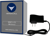
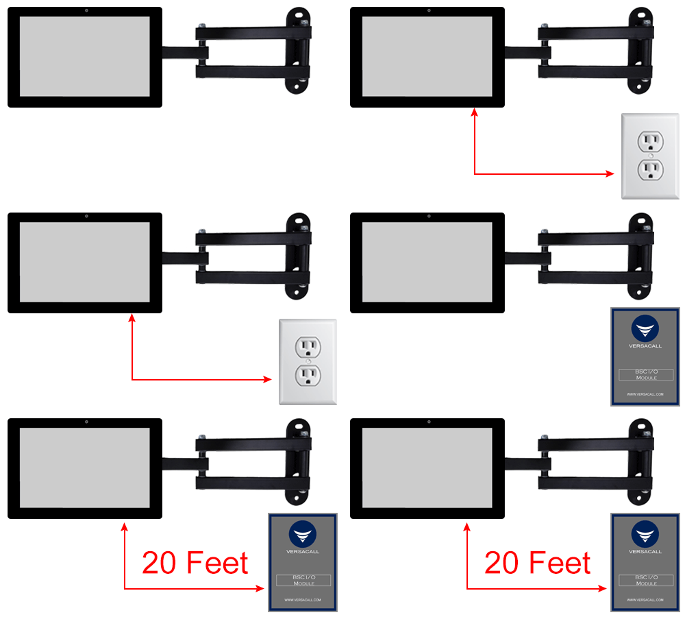
| | |A BSC Module is made up of a Touch Screen & an I/O Module. Both pieces must have acces to 110VAC power and a mounting location that places them within 15 feet of each other. | ||
|} | |} | ||
|} | |} | ||
{|style="margin:left;" | {|style="margin:left;" | ||
|valign="top" | | |valign="top" | | ||
{|class="wikitable" style="background:# | {|class="wikitable" style="background:#white; width: 800px;" | ||
|- | |- | ||
!colspan=" | !colspan="2"|<big>'''Hardware Components'''</big> | ||
|- | |- | ||
|[[File:bscin18.png]] || [[File:bscin1.png]] | |[[File:bscin18.png|center|200px]] || [[File:bscin1.png|center|200px]] | ||
|- | |- | ||
|Touch Screen || I/O Module | |align="center"|'''Touch Screen''' || align="center"|'''I/O Module''' | ||
|} | |} | ||
|} | |} | ||
<br> | |||
= | {|style="margin:left;" | ||
|valign="top" | | |||
{|class="wikitable mw-collapsible mw-collapsed" style="background:#eaf3ff; width: 800px;" | |||
!style="text-align: left;"|<big>'''Requirements'''</big> | |||
{| | |- | ||
|<big>'''Step 1 | |'''1.''' The VT3000 Core Software installed and running on your system. | ||
|- | |||
|'''2.''' Coordinator connected and communicating with your VersaCall system. | |||
|- | |||
|'''3.''' BSC Module - Touch Screen & I/O Module. | |||
|- | |||
|'''4.''' Two available 110VAC outlets at the BSC mounting location. | |||
|} | |||
|} | |||
=<big>'''Instructions'''</big>= | |||
<br> | |||
{|style="margin:left; width: 100px; background:#eaf3ff; padding:5px; border:2px solid #000000;" | |||
|- | |||
|<big>'''Step 1.'''</big> | |||
{|style="margin:left; width: 800px; background:#F0F0F0; padding:5px; border:2px solid #000000;" | |||
|valign="top" | | |||
|- | |||
|Mount IO Module within 6 feet of an electrical outlet. | |||
{|style="margin:left;" | |||
|valign="top" | | |||
{|class="wikitable" style=" align="center; " background:white;" | |||
|- | |- | ||
| | |[[File:Install_BSCWIO1.gif]] | ||
|} | |||
|} | |||
|} | |||
|} | |} | ||
<br> | |||
---- | |||
{| | <br> | ||
|<big>'''Step 2 | {|style="margin:left; width: 100px; background:#eaf3ff; padding:5px; border:2px solid #000000;" | ||
|- | |||
|<big>'''Step 2.'''</big> | |||
{|style="margin:left; width: 800px; background:#F0F0F0; padding:5px; border:2px solid #000000;" | |||
|valign="top" | | |||
|- | |||
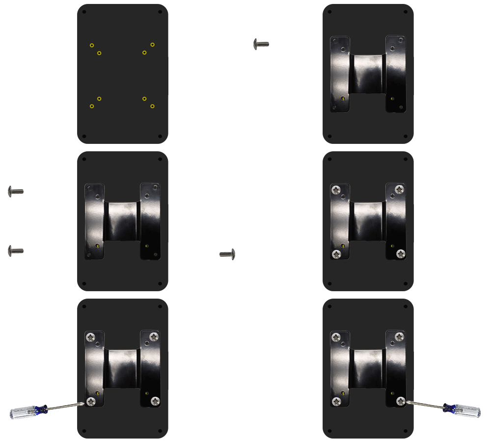
|Attach Touch Screen to the mount using the included screws. | |||
{|style="margin:left;" | |||
|valign="top" | | |||
{|class="wikitable" style="background:white;" | |||
|- | |- | ||
| | |[[File:Install_BSCNO1.gif]] | ||
|} | |||
|} | |||
|} | |||
|} | |} | ||
<br> | |||
---- | |||
{| | <br> | ||
|<big>'''Step 3 | {|style="margin:left; width: 100px; background:#eaf3ff; padding:5px; border:2px solid #000000;" | ||
|- | |||
|<big>'''Step 3.'''</big> | |||
{|style="margin:left; width: 800px; background:#F0F0F0; padding:5px; border:2px solid #000000;" | |||
|valign="top" | | |||
|- | |||
|Mount the Touch Screen within 6 feet of an electrical outlet & within 20 feet of the IO Module. | |||
{|style="margin:left;" | |||
|valign="top" | | |||
{|class="wikitable" style="background:white;" | |||
|- | |- | ||
| | |[[File:Install_BSCWIO2.gif]] | ||
|} | |||
|} | |||
|} | |} | ||
|} | |||
<br> | |||
{| | ---- | ||
|<big>'''Step 4 | <br> | ||
{|style="margin:left; width: 100px; background:#eaf3ff; padding:5px; border:2px solid #000000;" | |||
|- | |||
|<big>'''Step 4.'''</big> | |||
{|style="margin:left; width: 800px; background:#F0F0F0; padding:5px; border:2px solid #000000;" | |||
|valign="top" | | |||
|- | |||
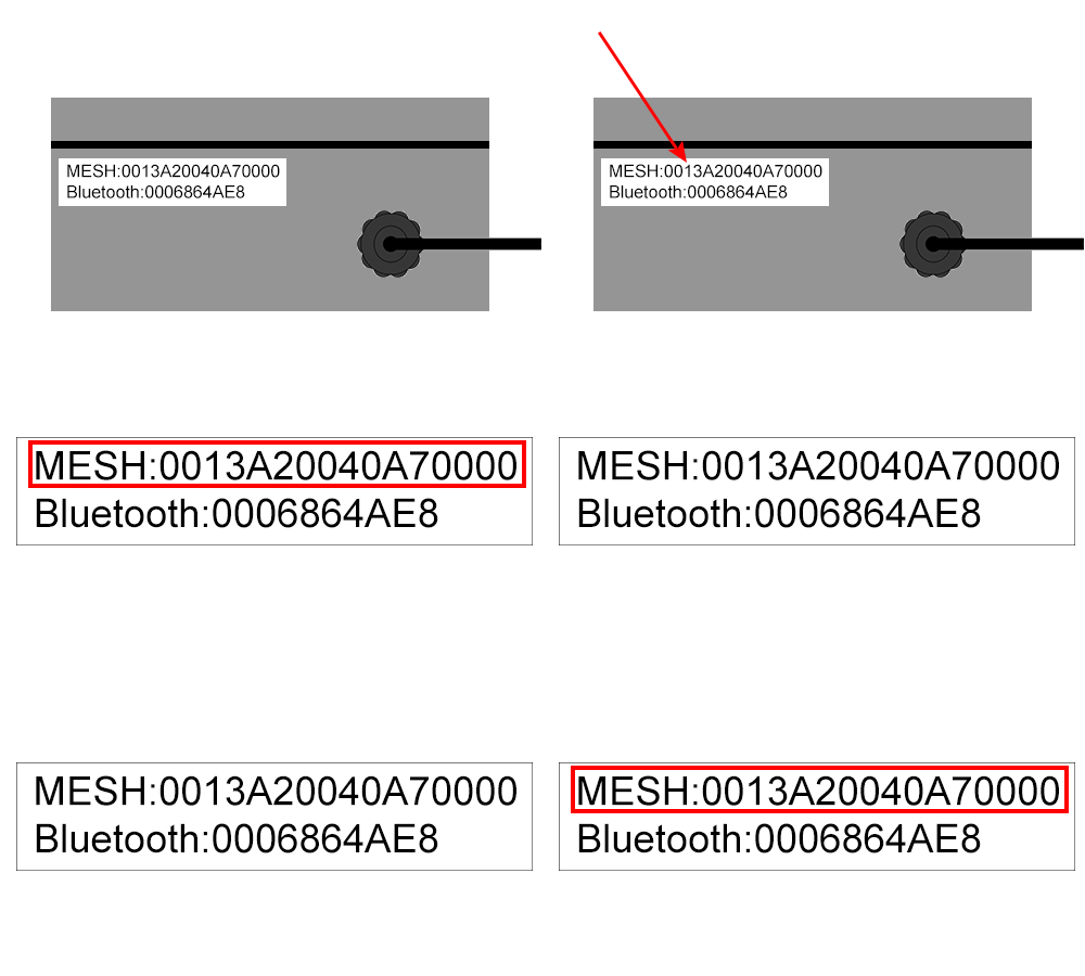
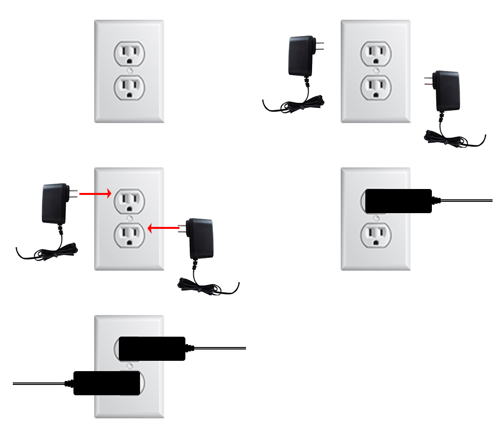
|Find & Note of the Mesh Address on IO Module. - plug in IO Module & the Touch Screen. | |||
{|style="margin:left;" | |||
|valign="top" | | |||
{|class="wikitable" style="background:white;" | |||
|- | |- | ||
| | |[[File:Install PSM4.gif]] | ||
|} | |||
|} | |||
|} | |||
|} | |} | ||
<br> | |||
---- | |||
{| | <br> | ||
|<big>'''Step 5 | {|style="margin:left; width: 100px; background:#eaf3ff; padding:5px; border:2px solid #000000;" | ||
|- | |||
|<big>'''Step 5.'''</big> | |||
{|style="margin:left; width: 800px; background:#F0F0F0; padding:5px; border:2px solid #000000;" | |||
|valign="top" | | |||
|- | |||
|Plug in the IO Module & Touch Screen power. | |||
{|style="margin:left;" | |||
|valign="top" | | |||
{|class="wikitable" style="background:white;" | |||
|- | |- | ||
| | |[[File:Install PSM5.gif]] | ||
|} | |||
|} | |||
|} | |||
|} | |} | ||
<br> | |||
---- | |||
{| | <br> | ||
|<big>'''Step 6 | {|style="margin:left; width: 100px; background:#eaf3ff; padding:5px; border:2px solid #000000;" | ||
|- | |||
|<big>'''Step 6.'''</big> | |||
{|style="margin:left; width: 800px; background:#F0F0F0; padding:5px; border:2px solid #000000;" | |||
|valign="top" | | |||
|- | |||
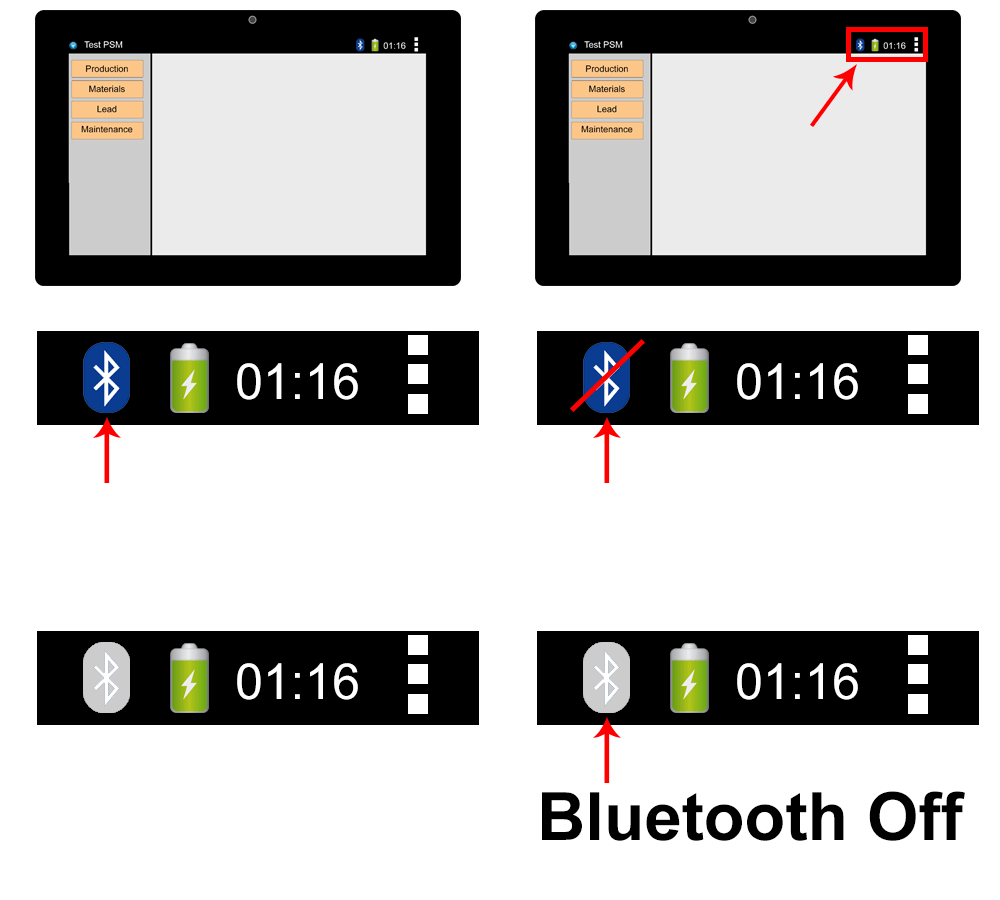
|The IO Module & Touch Screen will automatically connect - verify Bluetooth connection on the Touch Screen. | |||
{|style="margin:left;" | |||
|valign="top" | | |||
{|class="wikitable" style="background:white;" | |||
|- | |- | ||
| | |[[File:Install PSM6.gif]] | ||
|} | |||
|} | |||
|} | |} | ||
|} | |||
<br> | |||
---- | |||
{| | <br> | ||
|<big>'''Step 7 | {|style="margin:left; width: 100px; background:#eaf3ff; padding:5px; border:2px solid #000000;" | ||
|- | |||
|<big>'''Step 7.'''</big> | |||
{|style="margin:left; width: 800px; background:#F0F0F0; padding:5px; border:2px solid #000000;" | |||
|valign="top" | | |||
|- | |||
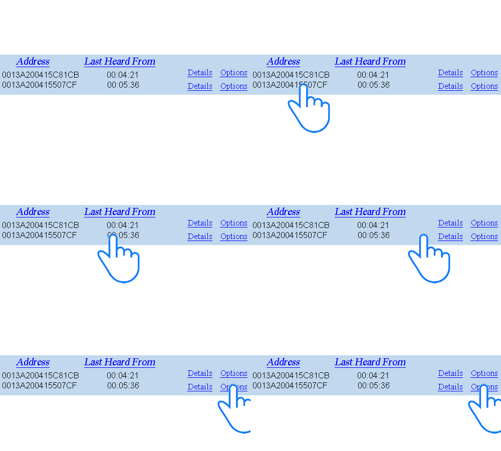
|Open VT3000 Core Software select Diagnostics - select Device Status. | |||
{|style="margin:left;" | |||
|valign="top" | | |||
{|class="wikitable" style="background:white;" | |||
|- | |- | ||
| | |[[File:Install PSM7.gif]] | ||
|} | |||
|} | |||
|} | |||
|} | |} | ||
<br> | |||
---- | |||
<br> | |||
{| | {|style="margin:left; width: 100px; background:#eaf3ff; padding:5px; border:2px solid #000000;" | ||
|<big>'''Step 8 | |- | ||
|<big>'''Step 8.'''</big> | |||
{|style="margin:left; width: 800px; background:#F0F0F0; padding:5px; border:2px solid #000000;" | |||
|valign="top" | | |||
|- | |||
|Find the IO Mesh Address in the Address field - select Options link on the right. | |||
{|style="margin:left;" | |||
|valign="top" | | |||
{|class="wikitable" style="background:white;" | |||
|- | |- | ||
| | |[[File:Install PSM8.gif]] | ||
|} | |||
|} | |||
|} | |||
|} | |} | ||
<br> | |||
---- | |||
{| | <br> | ||
|<big>'''Step 9 | {|style="margin:left; width: 100px; background:#eaf3ff; padding:5px; border:2px solid #000000;" | ||
|- | |||
|<big>'''Step 9.'''</big> | |||
{|style="margin:left; width: 800px; background:#F0F0F0; padding:5px; border:2px solid #000000;" | |||
|valign="top" | | |||
|- | |||
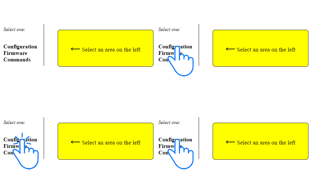
|Select Configuration. | |||
{|style="margin:left;" | |||
|valign="top" | | |||
{|class="wikitable" style="background:white;" | |||
|- | |- | ||
| | |[[File:Install PSM9.gif]] | ||
|} | |||
|} | |||
|} | |} | ||
|} | |||
<br> | |||
{| | ---- | ||
|<big>'''Step 10 | <br> | ||
{|style="margin:left; width: 100px; background:#eaf3ff; padding:5px; border:2px solid #000000;" | |||
|- | |||
|<big>'''Step 10.'''</big> | |||
{|style="margin:left; width: 800px; background:#F0F0F0; padding:5px; border:2px solid #000000;" | |||
|valign="top" | | |||
|- | |||
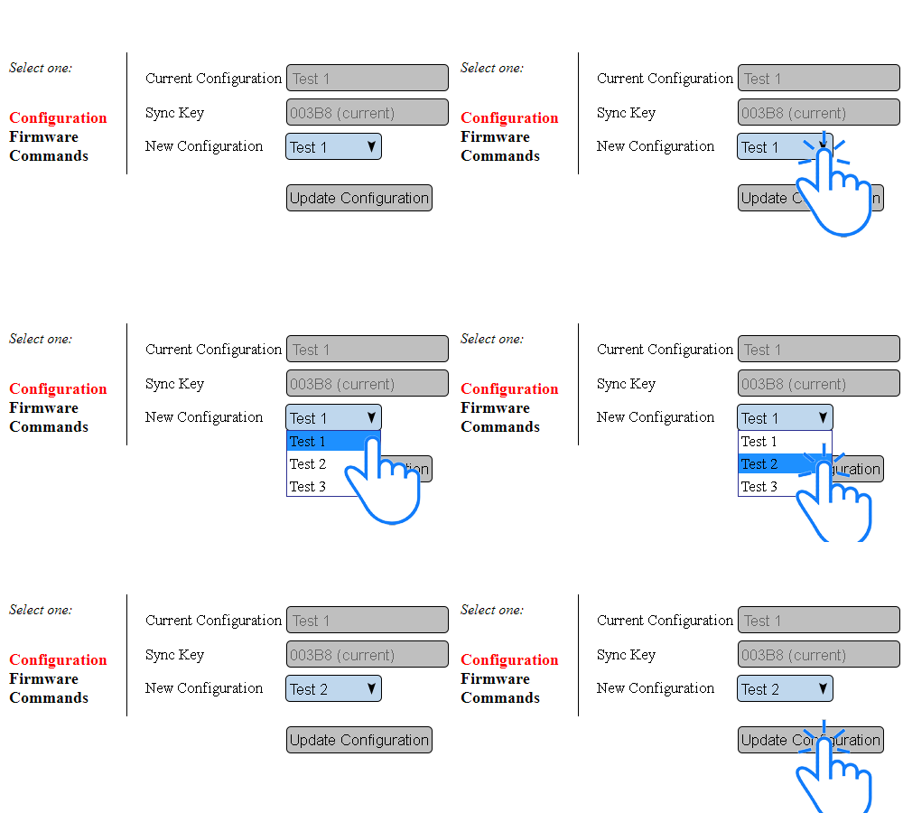
|Select a Device Configuration from the New Configuration field - select Update Configuration button. | |||
{|style="margin:left;" | |||
|valign="top" | | |||
{|class="wikitable" style="background:white;" | |||
|- | |- | ||
| | |[[File:ConfigMaster1.gif]] | ||
|} | |||
|} | |||
|} | |||
|} | |} | ||
<br> | |||
---- | |||
{| | <br> | ||
|<big>'''Step 11 | {|style="margin:left; width: 100px; background:#eaf3ff; padding:5px; border:2px solid #000000;" | ||
|- | |||
|<big>'''Step 11.'''</big> | |||
{|style="margin:left; width: 800px; background:#F0F0F0; padding:5px; border:2px solid #000000;" | |||
|valign="top" | | |||
|- | |||
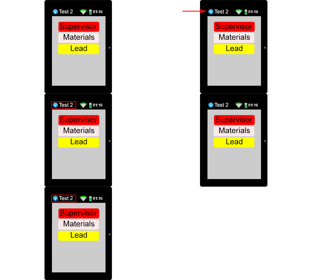
|Go to the Touch Screen - verify the correct module name shows in the top left corner. | |||
{|style="margin:left;" | |||
|valign="top" | | |||
{|class="wikitable" style="background:white;" | |||
|- | |- | ||
| | |[[File:Install BSCNO5.gif]] | ||
|} | |||
|} | |||
|} | |||
|} | |} | ||
<br> | |||
---- | ---- | ||
---- | ---- | ||
Revision as of 14:26, 17 September 2021
|
| ||||||
|
Instructions
Step 1.
|
Step 2.
|
Step 3.
|
Step 4.
|
Step 5.
|
Step 6.
|
Step 7.
|
Step 8.
|
Step 9.
|
Step 10.
|
Step 11.
|
|
| ||||||||

