Difference between revisions of "VPIV - Create an Andon Grid Panel"
Jump to navigation
Jump to search
SupportAdmin (talk | contribs) |
SupportAdmin (talk | contribs) m (Text replacement - "https://www.linkedin.com/company/versacall-technologies-inc-/mycompany/" to "https://www.linkedin.com/company/versacall/") |
||
| (14 intermediate revisions by the same user not shown) | |||
| Line 1: | Line 1: | ||
= | {|style="background:transparent; color:black" border="0" height="230" align="center" valign="bottom" | ||
|+style="background:transparent| | |||
|-align="center" | |||
| | |||
|[[Image:CallUsBtn.png|Call Now 858-677-6766]] | |||
[[ | | | ||
|[[Image:SubmitTckBtn.png|link=https://www.versacall.com/customer-support/service-ticket]] | |||
| | |||
|[[Image:EmailUsBtn.png|link=mailto:[email protected]?Subject=Help%20Needed%20Wiki&body=Type%20Message%20Here]] | |||
|} | |||
<br> | |||
---- | |||
---- | |||
''' | <br> | ||
[[File:GeneralHeader.png]] | |||
<br> | |||
{|style="margin:left; width: 100px; background:#eaf3ff; padding:5px; border:2px solid #000000;" | |||
|- | |||
|<big>'''Overview'''</big> | |||
{|style="margin:left; width: 800px; background:#F0F0F0; padding:5px; border:2px solid #000000;" | |||
= | |valign="top" | | ||
|- | |||
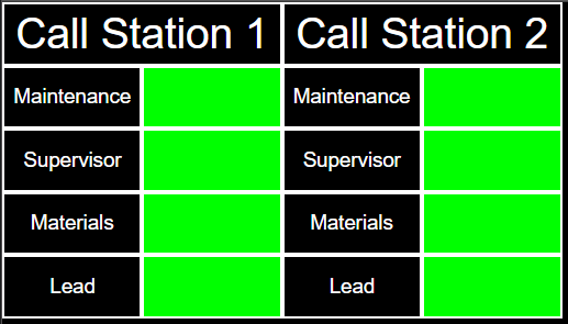
''' | |Grid Panels allow the user to add a cell to the panel then place it anywhere on the screen as well as allowing for complete control over all cell properties. An Andon Grid Panel/Widget will show the state and duration of an alarm on any type of device. The state of the alarm can be used to create color changes in the cell. Our example is of a standard bingo board for one call station with 4 buttons/calls. | ||
|- | |||
|style= "text-align:center" | '''NOTE''' - The instructions below apply to both a Panel & a Widget. Both are created exactly the same. | |||
|} | |||
|} | |||
''' | <br> | ||
{|style="margin:left; width: 100px; background:#eaf3ff; padding:5px; border:2px solid #000000;" | |||
|- | |||
|<big>'''Requirements'''</big> | |||
{|style="margin:left; width: 800px; background:#F0F0F0; padding:5px; border:2px solid #000000;" | |||
=== | |valign="top" | | ||
{| class="wikitable mw-collapsible mw-collapsed" width="775px;" | |||
'''1.''' | |- | ||
|style="text-align: center;" | '''See Requirements Here''' | |||
|- | |||
|'''1.''' The VT3000 Core Software installed and running on your system. | |||
|- | |||
|'''2.''' VPIV - Virtual Panels IV software installed and running on your system. | |||
|- | |||
|'''3.''' In order to create this type of panel you will need at least one module setup with 1 or more Alarms. | |||
'''2.''' | |- | ||
|'''4.''' If you plan on showing an image on the panel, ensure you have uploaded it to VPIV using the Media section of the software. | |||
|} | |||
|} | |||
|} | |||
''' | <br> | ||
{|style="margin:left; width: 100px; background:#eaf3ff; padding:5px; border:2px solid #000000;" | |||
|- | |||
|<big>'''Panel Capabilities'''</big> | |||
{|style="margin:left; width: 800px; background:#F0F0F0; padding:5px; border:2px solid #000000;" | |||
''' | |valign="top" | | ||
{| class="wikitable mw-collapsible mw-collapsed" width="775px;" | |||
|- | |||
|style="text-align: center;" | '''See Capabilities Here''' | |||
|- | |||
|'''1. Tags''' - Constant, State, Duration & System Property. | |||
= | |- | ||
|'''2. Widgets''' - Andon & Information. | |||
|- | |||
''' | |'''3. URL''' - Not Available. | ||
|- | |||
|'''4. Real-Time Reports''' - Not Available. | |||
[[File: | |} | ||
|} | |||
|} | |||
<br> | |||
{|style="margin:left; width: 100px; background:#eaf3ff; padding:5px; border:2px solid #000000;" | |||
[[File: | |- | ||
|<big>'''Example'''</big> | |||
{|style="margin:left; width: 800px; background:#F0F0F0; padding:5px; border:2px solid #000000;" | |||
''' | |valign="top" | | ||
|- | |||
|[[File:ANGrid1.png|center|517px]] | |||
|} | |||
|} | |||
==== | <br> | ||
---- | |||
---- | |||
'' | <br> | ||
[[File:InstructionHeader.png]] | |||
<br> | |||
{|style="margin:left; width: 100px; background:#eaf3ff; padding:5px; border:2px solid #000000;" | |||
|- | |||
|<big>'''Step 1.'''</big> | |||
{|style="margin:left; width: 800px; background:#F0F0F0; padding:5px; border:2px solid #000000;" | |||
|valign="top" | | |||
[[File: | |- | ||
|Open the VT3000 web interface - select VPIV button from the welcome page. | |||
{|style="margin:left;" | |||
|valign="top" | | |||
{|class="wikitable" style=" align="center; " background:white;" | |||
[[File: | |- | ||
|[[File:VPImage1.png|center|257px]] | |||
|} | |||
|} | |||
'' | |} | ||
|} | |||
<br> | |||
---- | |||
<br> | |||
{|style="margin:left; width: 100px; background:#eaf3ff; padding:5px; border:2px solid #000000;" | |||
|- | |||
|<big>'''Step 2.'''</big> | |||
[[File: | {|style="margin:left; width: 800px; background:#F0F0F0; padding:5px; border:2px solid #000000;" | ||
|valign="top" | | |||
|- | |||
|Select either the Panels or Widgets icon depending on which type you want to create. | |||
''' | {|style="margin:left;" | ||
|valign="top" | | |||
{|class="wikitable" style="background:white;" | |||
|- | |||
|[[File:VPIV_Panels.png|center|103px]] || [[File:VPIV_Widgets.png|center|103px]] | |||
|} | |||
==== | |} | ||
|} | |||
|} | |||
<br> | |||
---- | |||
<br> | |||
{|style="margin:left; width: 100px; background:#eaf3ff; padding:5px; border:2px solid #000000;" | |||
|- | |||
'' | |<big>'''Step 3.'''</big> | ||
{|style="margin:left; width: 800px; background:#F0F0F0; padding:5px; border:2px solid #000000;" | |||
|valign="top" | | |||
|- | |||
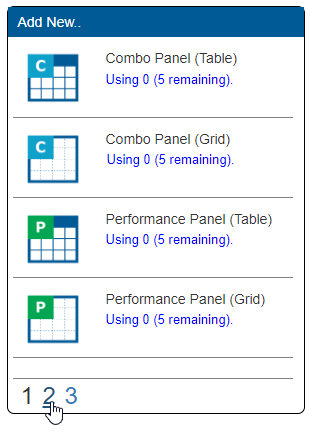
|When creating a Panel, select page 2 on the Add New menu. When creating a Widget, no page selection is required. | |||
{|style="margin:left;" | |||
|valign="top" | | |||
{|class="wikitable" style="background:white;" | |||
|- | |||
|[[File:Inform5.png|center|314px]] | |||
|} | |||
|} | |||
[[File: | |} | ||
|} | |||
<br> | |||
---- | |||
<br> | |||
{|style="margin:left; width: 100px; background:#eaf3ff; padding:5px; border:2px solid #000000;" | |||
|- | |||
|<big>'''Step 4.'''</big> | |||
'''6.''' | {|style="margin:left; width: 800px; background:#F0F0F0; padding:5px; border:2px solid #000000;" | ||
|valign="top" | | |||
|- | |||
|Select the Andon Table Panel/Wdiget Icon in the list. | |||
{|style="margin:left;" | |||
|valign="top" | | |||
{|class="wikitable" style="background:white;" | |||
|- | |||
|[[File:AndonGrid.png|center|56px]] | |||
|} | |||
|} | |||
|} | |||
[[File: | |} | ||
<br> | |||
---- | |||
<br> | |||
{|style="margin:left; width: 100px; background:#eaf3ff; padding:5px; border:2px solid #000000;" | |||
|- | |||
|<big>'''Step 5.'''</big> | |||
{|style="margin:left; width: 800px; background:#F0F0F0; padding:5px; border:2px solid #000000;" | |||
|valign="top" | | |||
|- | |||
|Select the Properties tab at the top of the screen. | |||
''' | {|style="margin:left;" | ||
|valign="top" | | |||
{|class="wikitable" style="background:white;" | |||
|- | |||
|[[File:VPIVPropTab.png|center|244px]] | |||
|} | |||
|} | |||
[[File: | |} | ||
|} | |||
<br> | |||
''' | ---- | ||
<br> | |||
[[File: | {|style="margin:left; width: 100px; background:#eaf3ff; padding:5px; border:2px solid #000000;" | ||
|- | |||
|<big>'''Step 6.'''</big> | |||
''' | {|style="margin:left; width: 800px; background:#F0F0F0; padding:5px; border:2px solid #000000;" | ||
|valign="top" | | |||
|- | |||
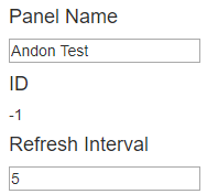
|Enter a name for the Panel/Widget in the Panel/Widget Name field under the Properties tab. Leave the Refresh Interval at 5. | |||
{|style="margin:left;" | |||
|valign="top" | | |||
{|class="wikitable" style="background:white;" | |||
[[ | |- | ||
|[[File:AndonPan1.png|center|188px]] | |||
|} | |||
''' | |} | ||
|} | |||
|} | |||
<br> | |||
---- | |||
<br> | |||
{|style="margin:left; width: 100px; background:#eaf3ff; padding:5px; border:2px solid #000000;" | |||
[[File: | |- | ||
|<big>'''Step 7.'''</big> | |||
{|style="margin:left; width: 800px; background:#F0F0F0; padding:5px; border:2px solid #000000;" | |||
''' | |valign="top" | | ||
|- | |||
|After entering a name for the Panel/Widget, select the Tags Tab at the top of the page. | |||
=== | {|style="margin:left;" | ||
|valign="top" | | |||
{|class="wikitable" style="background:white;" | |||
''' | |- | ||
|[[File:AndonPan2.png|center|227px]] | |||
|} | |||
|} | |||
|} | |||
|} | |||
<br> | |||
---- | |||
[[File: | <br> | ||
{|style="margin:left; width: 100px; background:#eaf3ff; padding:5px; border:2px solid #000000;" | |||
|- | |||
''' | |<big>'''Step 8.'''</big> | ||
{|style="margin:left; width: 800px; background:#F0F0F0; padding:5px; border:2px solid #000000;" | |||
|valign="top" | | |||
|- | |||
|On the Tag page, select the Add Tag icon. | |||
{|style="margin:left;" | |||
|valign="top" | | |||
{|class="wikitable" style="background:white;" | |||
|- | |||
|[[File:AndonPan3.png|center|220px]] | |||
''' | |} | ||
|} | |||
|} | |||
|} | |||
<br> | |||
=== | ---- | ||
<br> | |||
{|style="margin:left; width: 100px; background:#eaf3ff; padding:5px; border:2px solid #000000;" | |||
|- | |||
|<big>'''Step 9.'''</big> | |||
{|style="margin:left; width: 800px; background:#F0F0F0; padding:5px; border:2px solid #000000;" | |||
|valign="top" | | |||
|- | |||
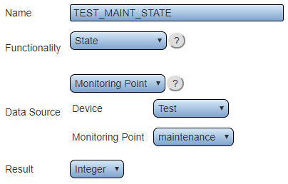
|Create a State tag for each alarm on each device that needs to be shown on the panel/widget. This is done so that we can use the tag to change the color of a cell to show Active (Red), Acknowledged (Yellow) & Not Active (Green). | |||
|- | |||
|style= "text-align:center" | <u>For more information on creating a State tag [[VPIV_State_Tag|'''Click Here''']]</u>. | |||
{|style="margin:left;" | |||
|valign="top" | | |||
{|class="wikitable" style="background:white; width:775px;" | |||
|- | |||
|[[File:AndonPan4.png|center|404px]] | |||
|} | |||
{|class="wikitable" style="background:white; width:775px;" | |||
|- | |||
|style= "text-align:left" | '''Name''' - enter a name for the tag - ensure it is something that you will recognize.. | |||
|- | |||
|style= "text-align:left" | '''Functionality''' - select State. | |||
|- | |||
|style= "text-align:left" | '''Data Source''' - select Monitoring Point. | |||
|- | |||
|style= "text-align:left" | '''Device''' - select the device that you want to setup. | |||
|- | |||
|style= "text-align:left" | '''Monitoring Point''' - select the Alarm/Call you want to setup. | |||
|- | |||
|style= "text-align:left" | '''Result''' - select Integer. | |||
|} | |||
|} | |||
|} | |||
|} | |||
<br> | |||
---- | |||
<br> | |||
{|style="margin:left; width: 100px; background:#eaf3ff; padding:5px; border:2px solid #000000;" | |||
|- | |||
|<big>'''Step 10.'''</big> | |||
{|style="margin:left; width: 800px; background:#F0F0F0; padding:5px; border:2px solid #000000;" | |||
|valign="top" | | |||
|- | |||
|Select the Add Tag icon. | |||
{|style="margin:left;" | |||
|valign="top" | | |||
{|class="wikitable" style="background:white;" | |||
|- | |||
|[[File:AndonPan3.png|center|220px]] | |||
|} | |||
|} | |||
|} | |||
|} | |||
<br> | |||
---- | |||
<br> | |||
{|style="margin:left; width: 100px; background:#eaf3ff; padding:5px; border:2px solid #000000;" | |||
|- | |||
|<big>'''Step 11.'''</big> | |||
{|style="margin:left; width: 800px; background:#F0F0F0; padding:5px; border:2px solid #000000;" | |||
|valign="top" | | |||
|- | |||
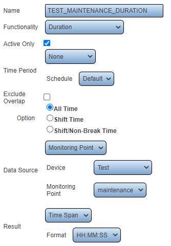
|Create a Duration tag for each alarm on each device that needs to be shown on the panel/widget. This will be used to show the active time the Alarm/Call has been active. | |||
|- | |||
|style= "text-align:center" | <u>For more information on creating a Duration tag [[VPIV_Duration_Tag|'''Click Here''']].</u> | |||
{|style="margin:left;" | |||
|valign="top" | | |||
{|class="wikitable" style="background:white; width:775px;" | |||
|- | |||
|[[File:AndonPan50.png|center|334px]] | |||
|} | |||
{|class="wikitable" style="background:white; width:775px;" | |||
|- | |||
|style= "text-align:left" | '''Name''' - enter a name for the tag - ensure it is something that you will recognize.. | |||
|- | |||
|style= "text-align:left" | '''Functionality''' - select Duration. | |||
|- | |||
|style= "text-align:left" | '''Active Only''' - select Active Only - we want the panel to show time only when an Alarm/Call is active or acknowledged. | |||
|- | |||
|style= "text-align:left" | '''Time Period''' - no selection is required as we are using the Active Only option. | |||
|- | |||
|style= "text-align:left" | '''Schedule''' - no selection is required as we are using the Active Only option. | |||
|- | |||
|style= "text-align:left" | '''Exclude Overlap''' - leave this unchecked - not required. | |||
|- | |||
|style= "text-align:left" | '''Option''' - select All Time. | |||
|- | |||
|style= "text-align:left" | '''Data Source''' - select Monitoring Point. | |||
|- | |||
|style= "text-align:left" | '''Device''' - select the device that you want to setup. | |||
|- | |||
|style= "text-align:left" | '''Monitoring Point''' - select the Alarm/Call you want to setup. | |||
|- | |||
|style= "text-align:left" | '''Result''' - select Time Span. | |||
|- | |||
|style= "text-align:left" | '''Format''' - select HH:MM:SS. | |||
|} | |||
|} | |||
|} | |||
|} | |||
<br> | |||
---- | |||
<br> | |||
{|style="margin:left; width: 100px; background:#eaf3ff; padding:5px; border:2px solid #000000;" | |||
|- | |||
|<big>'''Step 12.'''</big> | |||
{|style="margin:left; width: 800px; background:#F0F0F0; padding:5px; border:2px solid #000000;" | |||
|valign="top" | | |||
|- | |||
|After all of the State & Duration Tags are setup for the device(s) - click on the Save & Exit button in the top right corner of the screen. This is done as a good practice measure so that there is a lower risk of losing a connection/changes. | |||
{|style="margin:left;" | |||
|valign="top" | | |||
{|class="wikitable" style="background:white;" | |||
|- | |||
|[[File:VPSaveButton1.png|250px]] | |||
|} | |||
|} | |||
|} | |||
|} | |||
<br> | |||
---- | |||
<br> | |||
{|style="margin:left; width: 100px; background:#eaf3ff; padding:5px; border:2px solid #000000;" | |||
|- | |||
|<big>'''Step 13.'''</big> | |||
{|style="margin:left; width: 800px; background:#F0F0F0; padding:5px; border:2px solid #000000;" | |||
|valign="top" | | |||
|- | |||
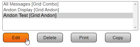
|You will be returned to the Panels/Widgets home page. Click on the Panel/Widget that you created in the steps above so that it is highlighted - click on the Edit button. | |||
{|style="margin:left;" | |||
|valign="top" | | |||
{|class="wikitable" style="background:white;" | |||
|- | |||
|[[File:AndonGrid50.png|476px]] | |||
|} | |||
|} | |||
|} | |||
|} | |||
<br> | |||
---- | |||
<br> | |||
{|style="margin:left; width: 100px; background:#eaf3ff; padding:5px; border:2px solid #000000;" | |||
|- | |||
|<big>'''Step 14.'''</big> | |||
{|style="margin:left; width: 800px; background:#F0F0F0; padding:5px; border:2px solid #000000;" | |||
|valign="top" | | |||
|- | |||
|Click on the Layout tab at the top of the page. | |||
{|style="margin:left;" | |||
|valign="top" | | |||
{|class="wikitable" style="background:white;" | |||
|- | |||
|[[File:AndonPan6.png|222px]] | |||
|} | |||
|} | |||
|} | |||
|} | |||
<br> | |||
---- | |||
<br> | |||
{|style="margin:left; width: 100px; background:#eaf3ff; padding:5px; border:2px solid #000000;" | |||
|- | |||
|<big>'''Step 15.'''</big> | |||
{|style="margin:left; width: 800px; background:#F0F0F0; padding:5px; border:2px solid #000000;" | |||
|valign="top" | | |||
|- | |||
|In this example, we will be making a panel for 2 modules that have the same 4 alarms/calls (Maintenance, Lead, Materials & Supervisor). To accomplish this you will need to add all of the Cells to the Grid. Use the Add Cell ('''+''') icon at the top left of the Grid. | |||
{|style="margin:left;" | |||
|valign="top" | | |||
{|class="wikitable" style="background:white;" | |||
|- | |||
|[[File:ANGrid2.png|191px]] | |||
|} | |||
|} | |||
|} | |||
|} | |||
<br> | |||
---- | |||
<br> | |||
{|style="margin:left; width: 100px; background:#eaf3ff; padding:5px; border:2px solid #000000;" | |||
|- | |||
|<big>'''Step 16.'''</big> | |||
{|style="margin:left; width: 800px; background:#F0F0F0; padding:5px; border:2px solid #000000;" | |||
|valign="top" | | |||
|- | |||
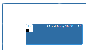
|A new cell will appear highlighted on the grid. | |||
{|style="margin:left;" | |||
|valign="top" | | |||
{|class="wikitable" style="background:white;" | |||
|- | |||
|[[File:ANGrid3.png|284px]] | |||
|} | |||
|} | |||
|} | |||
|} | |||
<br> | |||
---- | |||
<br> | |||
{|style="margin:left; width: 100px; background:#eaf3ff; padding:5px; border:2px solid #000000;" | |||
|- | |||
|<big>'''Step 17.'''</big> | |||
{|style="margin:left; width: 800px; background:#F0F0F0; padding:5px; border:2px solid #000000;" | |||
|valign="top" | | |||
|- | |||
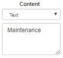
|Find the Content section at the bottom left of the Grid. By default the content field will be set to Text. Type in the name of the first alarm. For our example this will be Maintenance. | |||
{|style="margin:left;" | |||
|valign="top" | | |||
{|class="wikitable" style="background:white;" | |||
|- | |||
|[[File:ANGrid4.png|129px]] | |||
|} | |||
|} | |||
|} | |||
|} | |||
<br> | |||
---- | |||
<br> | |||
---- | |||
<br> | |||
{|style="margin:left; width: 100px; background:#eaf3ff; padding:5px; border:2px solid #000000;" | |||
|- | |||
|<big>'''Step 18.'''</big> | |||
{|style="margin:left; width: 800px; background:#F0F0F0; padding:5px; border:2px solid #000000;" | |||
|valign="top" | | |||
|- | |||
|Next we will add the Alarm state/duration cells to the right side of the button/call heading that was created. Click on the Add Cell icon. | |||
{|style="margin:left;" | |||
|valign="top" | | |||
{|class="wikitable" style="background:white;" | |||
|- | |||
|[[File:ANGrid2.png|191px]] | |||
|} | |||
|} | |||
|} | |||
|} | |||
<br> | |||
---- | |||
<br> | |||
{|style="margin:left; width: 100px; background:#eaf3ff; padding:5px; border:2px solid #000000;" | |||
|- | |||
|<big>'''Step 19.'''</big> | |||
{|style="margin:left; width: 800px; background:#F0F0F0; padding:5px; border:2px solid #000000;" | |||
|valign="top" | | |||
|- | |||
|With the new cell highlighted on the grid, find the Content section at the bottom left of the grid. | |||
{|style="margin:left;" | |||
|valign="top" | | |||
{|class="wikitable" style="background:white;" | |||
|- | |||
|[[File:ANGrid3.png|284px]] | |||
|} | |||
|} | |||
|} | |||
|} | |||
<br> | |||
---- | |||
<br> | |||
{|style="margin:left; width: 100px; background:#eaf3ff; padding:5px; border:2px solid #000000;" | |||
|- | |||
|<big>'''Step 20.'''</big> | |||
{|style="margin:left; width: 800px; background:#F0F0F0; padding:5px; border:2px solid #000000;" | |||
|valign="top" | | |||
|- | |||
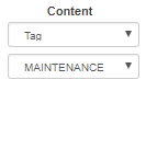
|Click on the down arrow for the Content field and select Tag. Select the Maintenance Duration tag for the first module/device. | |||
{|style="margin:left;" | |||
|valign="top" | | |||
{|class="wikitable" style="background:white;" | |||
|- | |||
|[[File:ANGrid6.png|133px]] | |||
|} | |||
|} | |||
|} | |||
|} | |||
<br> | |||
---- | |||
<br> | |||
{|style="margin:left; width: 100px; background:#eaf3ff; padding:5px; border:2px solid #000000;" | |||
|- | |||
|<big>'''Step 21.'''</big> | |||
{|style="margin:left; width: 800px; background:#F0F0F0; padding:5px; border:2px solid #000000;" | |||
|valign="top" | | |||
|- | |||
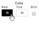
|To the right of the Content section, find the Colors section. Click on the Back color swatch. | |||
{|style="margin:left;" | |||
|valign="top" | | |||
{|class="wikitable" style="background:white;" | |||
|- | |||
|[[File:ANGrid7.png|136px]] | |||
|} | |||
|} | |||
|} | |||
|} | |||
<br> | |||
---- | |||
<br> | |||
{|style="margin:left; width: 100px; background:#eaf3ff; padding:5px; border:2px solid #000000;" | |||
|- | |||
|<big>'''Step 22.'''</big> | |||
{|style="margin:left; width: 800px; background:#F0F0F0; padding:5px; border:2px solid #000000;" | |||
|valign="top" | | |||
|- | |||
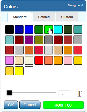
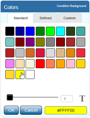
|Select the Green color swatch in the 1st row. Select the OK button after making the color selection. | |||
{|style="margin:left;" | |||
|valign="top" | | |||
{|class="wikitable" style="background:white;" | |||
|- | |||
|[[File:AndonPan23.png|303px]] | |||
|} | |||
|} | |||
|} | |||
|} | |||
<br> | |||
---- | |||
<br> | |||
{|style="margin:left; width: 100px; background:#eaf3ff; padding:5px; border:2px solid #000000;" | |||
|- | |||
|<big>'''Step 23.'''</big> | |||
{|style="margin:left; width: 800px; background:#F0F0F0; padding:5px; border:2px solid #000000;" | |||
|valign="top" | | |||
|- | |||
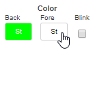
|In the Color section click on the Fore color swatch. | |||
{|style="margin:left;" | |||
|valign="top" | | |||
{|class="wikitable" style="background:white;" | |||
|- | |||
|[[File:ANGrid8.png|136px]] | |||
|} | |||
|} | |||
|} | |||
|} | |||
<br> | |||
---- | |||
<br> | |||
{|style="margin:left; width: 100px; background:#eaf3ff; padding:5px; border:2px solid #000000;" | |||
|- | |||
|<big>'''Step 24.'''</big> | |||
{|style="margin:left; width: 800px; background:#F0F0F0; padding:5px; border:2px solid #000000;" | |||
|valign="top" | | |||
|- | |||
|Select the Green color swatch in the 1st row. Select the OK button after making the color selection. | |||
{|style="margin:left;" | |||
|valign="top" | | |||
{|class="wikitable" style="background:white;" | |||
|- | |||
|[[File:AndonPan23.png|303px]] | |||
|} | |||
|} | |||
|} | |||
|} | |||
<br> | |||
---- | |||
<br> | |||
{|style="margin:left; width: 100px; background:#eaf3ff; padding:5px; border:2px solid #000000;" | |||
|- | |||
|<big>'''Step 25.'''</big> | |||
{|style="margin:left; width: 800px; background:#F0F0F0; padding:5px; border:2px solid #000000;" | |||
|valign="top" | | |||
|- | |||
|This creates the default status of the cell. When no alarms/calls are active the cell will be solid green. The duration tag you selected is in the cell but is made invisible by matching the Fore color to the Back color. | |||
|- | |||
|Next you will need to move the cell next to the alarm label. Using the Movement tools at the top of the grid, move the duration cell next to the Maintenance label. | |||
{|style="margin:left;" | |||
|valign="top" | | |||
{|class="wikitable" style="background:white;" | |||
|- | |||
|[[File:ANGrid9.png|267px]] | |||
|} | |||
|} | |||
|} | |||
|} | |||
<br> | |||
---- | |||
<br> | |||
{|style="margin:left; width: 100px; background:#eaf3ff; padding:5px; border:2px solid #000000;" | |||
|- | |||
|<big>'''Step 26.'''</big> | |||
{|style="margin:left; width: 800px; background:#F0F0F0; padding:5px; border:2px solid #000000;" | |||
|valign="top" | | |||
|- | |||
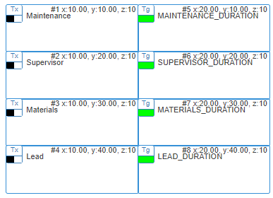
|When you are done moving the cell, your grid should look like the image below. | |||
{|style="margin:left;" | |||
|valign="top" | | |||
{|class="wikitable" style="background:white;" | |||
|- | |||
|[[File:ANGrid11.png|385px]] | |||
|} | |||
|} | |||
|} | |||
|} | |||
<br> | |||
---- | |||
<br> | |||
{|style="margin:left; width: 100px; background:#eaf3ff; padding:5px; border:2px solid #000000;" | |||
|- | |||
|<big>'''Step 27.'''</big> | |||
{|style="margin:left; width: 800px; background:#F0F0F0; padding:5px; border:2px solid #000000;" | |||
|valign="top" | | |||
|- | |||
|Repeat the cell creation steps for the remaining Alarms/Calls. When this process is completed your Grid should look similar to the image below. | |||
{|style="margin:left;" | |||
|valign="top" | | |||
{|class="wikitable" style="background:white;" | |||
|- | |||
|[[File:ANGrid10.png|387px]] | |||
|} | |||
|} | |||
|} | |||
|} | |||
<br> | |||
---- | |||
<br> | |||
{|style="margin:left; width: 100px; background:#eaf3ff; padding:5px; border:2px solid #000000;" | |||
|- | |||
|<big>'''Step 28.'''</big> | |||
{|style="margin:left; width: 800px; background:#F0F0F0; padding:5px; border:2px solid #000000;" | |||
|valign="top" | | |||
|- | |||
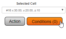
|Next we will be setting up conditions to turn the Duration Cell different colors based on the State of the Alarm/Call. Select the first Duration Cell that you created - find the Selected Cell section at the bottom of right the Grid. Select the Conditions button. | |||
|- | |||
|style= "text-align:center" | <u>For our example we will be using the default color scheme.</u> | |||
|- | |||
|style= "text-align:center" | '''Red Cell''' = Active Call. | |||
|- | |||
|style= "text-align:center" | '''Yellow Cell''' = Acknowledged Call. | |||
|- | |||
|style= "text-align:center" | '''Green Cell''' = No Active Calls/Default. | |||
{|style="margin:left;" | |||
|valign="top" | | |||
{|class="wikitable" style="background:white;" | |||
|- | |||
|[[File:ANGrid13.png|225px]] | |||
|} | |||
|} | |||
|} | |||
|} | |||
<br> | |||
---- | |||
<br> | |||
{|style="margin:left; width: 100px; background:#eaf3ff; padding:5px; border:2px solid #000000;" | |||
|- | |||
|<big>'''Step 29.'''</big> | |||
{|style="margin:left; width: 800px; background:#F0F0F0; padding:5px; border:2px solid #000000;" | |||
|valign="top" | | |||
|- | |||
|The Conditions menu will pop-up - select the Color tab. | |||
{|style="margin:left;" | |||
|valign="top" | | |||
{|class="wikitable" style="background:white;" | |||
|- | |||
|[[File:ANGrid14.png|315px]] | |||
|} | |||
|} | |||
|} | |||
|} | |||
<br> | |||
---- | |||
<br> | |||
{|style="margin:left; width: 100px; background:#eaf3ff; padding:5px; border:2px solid #000000;" | |||
|- | |||
|<big>'''Step 30.'''</big> | |||
{|style="margin:left; width: 800px; background:#F0F0F0; padding:5px; border:2px solid #000000;" | |||
|valign="top" | | |||
|- | |||
|Click on the Add Color Condition button. | |||
{|style="margin:left;" | |||
|valign="top" | | |||
{|class="wikitable" style="background:white;" | |||
|- | |||
|[[File:AndonPan29.png|168px]] | |||
|} | |||
|} | |||
|} | |||
|} | |||
<br> | |||
---- | |||
<br> | |||
{|style="margin:left; width: 100px; background:#eaf3ff; padding:5px; border:2px solid #000000;" | |||
|- | |||
|<big>'''Step 31.'''</big> | |||
{|style="margin:left; width: 800px; background:#F0F0F0; padding:5px; border:2px solid #000000;" | |||
|valign="top" | | |||
|- | |||
|Click on the down arrow in the Left Comparator field, select the appropriate state tag for the alarm & device. In this example we selected TEST1_MAINT_STATE. | |||
{|style="margin:left;" | |||
|valign="top" | | |||
{|class="wikitable" style="background:white;" | |||
|- | |||
|[[File:AndonPan30.png|250px]] | |||
|} | |||
|} | |||
|} | |||
|} | |||
<br> | |||
---- | |||
<br> | |||
{|style="margin:left; width: 100px; background:#eaf3ff; padding:5px; border:2px solid #000000;" | |||
|- | |||
|<big>'''Step 32.'''</big> | |||
{|style="margin:left; width: 800px; background:#F0F0F0; padding:5px; border:2px solid #000000;" | |||
|valign="top" | | |||
|- | |||
|Select the (=) sign from the middle/comparator field. | |||
{|style="margin:left;" | |||
|valign="top" | | |||
{|class="wikitable" style="background:white;" | |||
|- | |||
|[[File:AndonPan31.png|55px]] | |||
|} | |||
|} | |||
|} | |||
|} | |||
<br> | |||
---- | |||
<br> | |||
{|style="margin:left; width: 100px; background:#eaf3ff; padding:5px; border:2px solid #000000;" | |||
|- | |||
|<big>'''Step 33.'''</big> | |||
{|style="margin:left; width: 800px; background:#F0F0F0; padding:5px; border:2px solid #000000;" | |||
|valign="top" | | |||
|- | |||
|Type 1 for the Right Comparator field. | |||
{|style="margin:left;" | |||
|valign="top" | | |||
{|class="wikitable" style="background:white;" | |||
|- | |||
|[[File:AndonPan32.png|248px]] | |||
|} | |||
|} | |||
|} | |||
|} | |||
<br> | |||
---- | |||
<br> | |||
{|style="margin:left; width: 100px; background:#eaf3ff; padding:5px; border:2px solid #000000;" | |||
|- | |||
|<big>'''Step 34.'''</big> | |||
{|style="margin:left; width: 800px; background:#F0F0F0; padding:5px; border:2px solid #000000;" | |||
|valign="top" | | |||
|- | |||
|Below the Comparator fields, there will be color swatches. Click on the Back color swatch. | |||
{|style="margin:left;" | |||
|valign="top" | | |||
{|class="wikitable" style="background:white;" | |||
|- | |||
|[[File:AndonPan33.png|237px]] | |||
|} | |||
|} | |||
|} | |||
|} | |||
<br> | |||
---- | |||
<br> | |||
{|style="margin:left; width: 100px; background:#eaf3ff; padding:5px; border:2px solid #000000;" | |||
|- | |||
|<big>'''Step 35.'''</big> | |||
{|style="margin:left; width: 800px; background:#F0F0F0; padding:5px; border:2px solid #000000;" | |||
|valign="top" | | |||
|- | |||
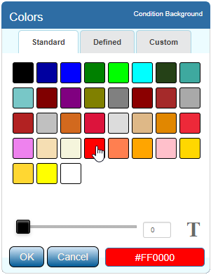
|On the Colors pop-up menu, select the Red color swatch on the 4th row. Click on the OK button. | |||
{|style="margin:left;" | |||
|valign="top" | | |||
{|class="wikitable" style="background:white;" | |||
|- | |||
|[[File:AndonPan34.png|301px]] | |||
|} | |||
|} | |||
|} | |||
|} | |||
<br> | |||
---- | |||
<br> | |||
{|style="margin:left; width: 100px; background:#eaf3ff; padding:5px; border:2px solid #000000;" | |||
|- | |||
|<big>'''Step 36.'''</big> | |||
{|style="margin:left; width: 800px; background:#F0F0F0; padding:5px; border:2px solid #000000;" | |||
|valign="top" | | |||
|- | |||
|This sets up the color condition for when a call has been activated but not acknowledged. Click on the OK option next to the Right Comparator field above the color swatches. | |||
{|style="margin:left;" | |||
|valign="top" | | |||
{|class="wikitable" style="background:white;" | |||
|- | |||
|[[File:AndonPan35.png|341px]] | |||
|} | |||
|} | |||
|} | |||
|} | |||
<br> | |||
---- | |||
<br> | |||
{|style="margin:left; width: 100px; background:#eaf3ff; padding:5px; border:2px solid #000000;" | |||
|- | |||
|<big>'''Step 37.'''</big> | |||
{|style="margin:left; width: 800px; background:#F0F0F0; padding:5px; border:2px solid #000000;" | |||
|valign="top" | | |||
|- | |||
|Next we will be setting up the color condition for an Acknowledged Alarm/Call. Click on the Add Color Condition button. | |||
{|style="margin:left;" | |||
|valign="top" | | |||
{|class="wikitable" style="background:white;" | |||
|- | |||
|[[File:AndonPan29.png|168px]] | |||
|} | |||
|} | |||
|} | |||
|} | |||
<br> | |||
---- | |||
<br> | |||
{|style="margin:left; width: 100px; background:#eaf3ff; padding:5px; border:2px solid #000000;" | |||
|- | |||
|<big>'''Step 38.'''</big> | |||
{|style="margin:left; width: 800px; background:#F0F0F0; padding:5px; border:2px solid #000000;" | |||
|valign="top" | | |||
|- | |||
|Click on the down arrow in the Left Comparator field, select the same state tag as you did in the steps above. In this example we selected TEST1_MAINT_STATE. | |||
{|style="margin:left;" | |||
|valign="top" | | |||
{|class="wikitable" style="background:white;" | |||
|- | |||
|[[File:AndonPan30.png|250px]] | |||
|} | |||
|} | |||
|} | |||
|} | |||
<br> | |||
---- | |||
<br> | |||
{|style="margin:left; width: 100px; background:#eaf3ff; padding:5px; border:2px solid #000000;" | |||
|- | |||
|<big>'''Step 39.'''</big> | |||
{|style="margin:left; width: 800px; background:#F0F0F0; padding:5px; border:2px solid #000000;" | |||
|valign="top" | | |||
|- | |||
|Select the (=) sign from the middle/comparator field. | |||
{|style="margin:left;" | |||
|valign="top" | | |||
{|class="wikitable" style="background:white;" | |||
|- | |||
|[[File:AndonPan31.png|55px]] | |||
|} | |||
|} | |||
|} | |||
|} | |||
<br> | |||
---- | |||
<br> | |||
{|style="margin:left; width: 100px; background:#eaf3ff; padding:5px; border:2px solid #000000;" | |||
|- | |||
|<big>'''Step 40.'''</big> | |||
{|style="margin:left; width: 800px; background:#F0F0F0; padding:5px; border:2px solid #000000;" | |||
|valign="top" | | |||
|- | |||
|Type 2 for the Right Comparator field. | |||
{|style="margin:left;" | |||
|valign="top" | | |||
{|class="wikitable" style="background:white;" | |||
|- | |||
|[[File:AndonPan36.png|248px]] | |||
|} | |||
|} | |||
|} | |||
|} | |||
<br> | |||
---- | |||
<br> | |||
{|style="margin:left; width: 100px; background:#eaf3ff; padding:5px; border:2px solid #000000;" | |||
|- | |||
|<big>'''Step 41.'''</big> | |||
{|style="margin:left; width: 800px; background:#F0F0F0; padding:5px; border:2px solid #000000;" | |||
|valign="top" | | |||
|- | |||
|Click on the Back color swatch. | |||
{|style="margin:left;" | |||
|valign="top" | | |||
{|class="wikitable" style="background:white;" | |||
|- | |||
|[[File:AndonPan33.png|237px]] | |||
|} | |||
|} | |||
|} | |||
|} | |||
<br> | |||
---- | |||
<br> | |||
{|style="margin:left; width: 100px; background:#eaf3ff; padding:5px; border:2px solid #000000;" | |||
|- | |||
|<big>'''Step 42.'''</big> | |||
{|style="margin:left; width: 800px; background:#F0F0F0; padding:5px; border:2px solid #000000;" | |||
|valign="top" | | |||
|- | |||
|On the Colors pop-up menu, select the Yellow color swatch on the 5th row. Click on the OK button. | |||
{|style="margin:left;" | |||
|valign="top" | | |||
{|class="wikitable" style="background:white;" | |||
|- | |||
|[[File:AndonPan37.png|302px]] | |||
|} | |||
|} | |||
|} | |||
|} | |||
<br> | |||
---- | |||
<br> | |||
{|style="margin:left; width: 100px; background:#eaf3ff; padding:5px; border:2px solid #000000;" | |||
|- | |||
|<big>'''Step 43.'''</big> | |||
{|style="margin:left; width: 800px; background:#F0F0F0; padding:5px; border:2px solid #000000;" | |||
|valign="top" | | |||
|- | |||
|This sets up the color condition for when a call has been acknowledged but not cleared. Click on the OK option next to the Right Comparator field above the color swatches. | |||
{|style="margin:left;" | |||
|valign="top" | | |||
{|class="wikitable" style="background:white;" | |||
|- | |||
|[[File:AndonPan35.png|341px]] | |||
|} | |||
|} | |||
|} | |||
|} | |||
<br> | |||
---- | |||
<br> | |||
{|style="margin:left; width: 100px; background:#eaf3ff; padding:5px; border:2px solid #000000;" | |||
|- | |||
|<big>'''Step 44.'''</big> | |||
{|style="margin:left; width: 800px; background:#F0F0F0; padding:5px; border:2px solid #000000;" | |||
|valign="top" | | |||
|- | |||
|When both Color Conditions have been setup and saved, click on the "X" button to close the Conditions menu. | |||
{|style="margin:left;" | |||
|valign="top" | | |||
{|class="wikitable" style="background:white;" | |||
|- | |||
|[[File:AndonPan38.png|90px]] | |||
|} | |||
|} | |||
|} | |||
|} | |||
<br> | |||
---- | |||
<br> | |||
{|style="margin:left; width: 100px; background:#eaf3ff; padding:5px; border:2px solid #000000;" | |||
|- | |||
|<big>'''Step 45.'''</big> | |||
{|style="margin:left; width: 800px; background:#F0F0F0; padding:5px; border:2px solid #000000;" | |||
|valign="top" | | |||
|- | |||
|Next we will need to add a Station Name label above the Alarm/Call cells. Click on the Add icon at the top left of the grid. | |||
{|style="margin:left;" | |||
|valign="top" | | |||
{|class="wikitable" style="background:white;" | |||
|- | |||
|[[File:ANGrid2.png|191px]] | |||
|} | |||
|} | |||
|} | |||
|} | |||
<br> | |||
---- | |||
<br> | |||
{|style="margin:left; width: 100px; background:#eaf3ff; padding:5px; border:2px solid #000000;" | |||
|- | |||
|<big>'''Step 46.'''</big> | |||
{|style="margin:left; width: 800px; background:#F0F0F0; padding:5px; border:2px solid #000000;" | |||
|valign="top" | | |||
|- | |||
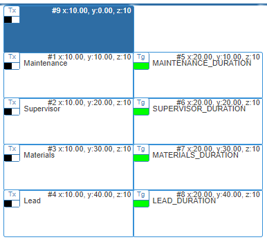
|Using the Movement tools, place the cell at the top of the group of cells you have created. Your grid should look similar to the image below. | |||
{|style="margin:left;" | |||
|valign="top" | | |||
{|class="wikitable" style="background:white;" | |||
|- | |||
|[[File:ANGrid15.png|386px]] | |||
|} | |||
|} | |||
|} | |||
|} | |||
<br> | |||
---- | |||
<br> | |||
{|style="margin:left; width: 100px; background:#eaf3ff; padding:5px; border:2px solid #000000;" | |||
|- | |||
|<big>'''Step 47.'''</big> | |||
{|style="margin:left; width: 800px; background:#F0F0F0; padding:5px; border:2px solid #000000;" | |||
|valign="top" | | |||
|- | |||
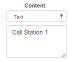
|With the cell highlighted, find the Content section at the bottom left of the grid. Text will be selected by default, enter the name of the station in the field below. In our example we entered Call Station 1. | |||
{|style="margin:left;" | |||
|valign="top" | | |||
{|class="wikitable" style="background:white;" | |||
|- | |||
|[[File:ANGrid17.png|138px]] | |||
|} | |||
|} | |||
|} | |||
|} | |||
<br> | |||
---- | |||
<br> | |||
{|style="margin:left; width: 100px; background:#eaf3ff; padding:5px; border:2px solid #000000;" | |||
|- | |||
|<big>'''Step 48.'''</big> | |||
{|style="margin:left; width: 800px; background:#F0F0F0; padding:5px; border:2px solid #000000;" | |||
|valign="top" | | |||
|- | |||
|With the cell still highlighted, find the Size toolbox at the top of the grid. We need to extend the length of the title cell to go across both the label & duration cells you created. Use the extend icon to expand the cell to cover both cells. | |||
{|style="margin:left;" | |||
|valign="top" | | |||
{|class="wikitable" style="background:white;" | |||
|- | |||
|[[File:ANGrid16.png|143px]] | |||
|} | |||
|} | |||
|} | |||
|} | |||
<br> | |||
---- | |||
<br> | |||
{|style="margin:left; width: 100px; background:#eaf3ff; padding:5px; border:2px solid #000000;" | |||
|- | |||
|<big>'''Step 49.'''</big> | |||
{|style="margin:left; width: 800px; background:#F0F0F0; padding:5px; border:2px solid #000000;" | |||
|valign="top" | | |||
|- | |||
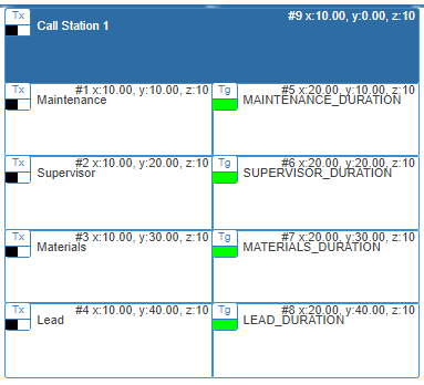
|When you are done expanding the cell, your grid should look like the image below. | |||
{|style="margin:left;" | |||
|valign="top" | | |||
{|class="wikitable" style="background:white;" | |||
|- | |||
|[[File:ANGrid18.png|383px]] | |||
|} | |||
|} | |||
|} | |||
|} | |||
<br> | |||
---- | |||
<br> | |||
{|style="margin:left; width: 100px; background:#eaf3ff; padding:5px; border:2px solid #000000;" | |||
|- | |||
|<big>'''Step 50.'''</big> | |||
{|style="margin:left; width: 800px; background:#F0F0F0; padding:5px; border:2px solid #000000;" | |||
|valign="top" | | |||
|- | |||
|Repeat the process for any additional Stations/Locations that you want to add to this panel. Once everything you need has been added, select the Save & Exit button at the top right corner of the table | |||
{|style="margin:left;" | |||
|valign="top" | | |||
{|class="wikitable" style="background:white;" | |||
|- | |||
|[[File:VPSaveButton1.png|250px]] | |||
|} | |||
|} | |||
|} | |||
|} | |||
<br> | |||
---- | |||
---- | |||
<br> | |||
{|style="margin:auto;" | |||
|+ | |||
[[File:RelatedHowTos.png|center]] | |||
|align="center" | | |||
{| class="wikitable mw-collapsible mw-collapsed" width="400px;" | |||
|- | |||
|style="text-align: center;" | '''Select a Guide Here''' | |||
|- | |||
|[[VPIV - Create/Edit Rotating Panels|Create a Rotating Panel]] | |||
|- | |||
|[[VPIV - Create a Messaging Panel|Create a Messaging Panel]] | |||
|- | |||
|[[VPIV - Create an Informative Table Panel|Create an Informative Panel]] | |||
|- | |||
|[[VPIV - Create an Andon Table Panel|Create an Andon (Table) Panel]] | |||
|- | |||
|[[VPIV - Create a Performance Table Panel|Create a Performance (Table) Panel]] | |||
|} | |||
|} | |||
<br> | |||
---- | |||
<br> | |||
{|style="margin:auto;" | |||
|+ | |||
[[File:SearchHeader.png|center]] | |||
|align="center" | | |||
{|class="wikitable" | |||
|- | |||
|<inputbox>type=search</inputbox> | |||
|} | |||
|} | |||
<br> | |||
---- | |||
<br> | |||
[[File:VC Footer.png|center]] | |||
{|style="background:transparent; color:black" border="0" height="200" align="center" valign="bottom" cellpadding=10px cellspacing=10px | |||
|+style="background:transparent| | |||
|-align="center" | |||
| | |||
|[[File:LinkedIn.png|Follow Us On LinkedIn|link=https://www.linkedin.com/company/versacall/]] | |||
| | |||
|[[File:BlogIcon.png|View our Blog|link=https://www.versacall.com/blog/]] | |||
|} | |||
<br> | |||
[[Category:Virtual Panels IV]] | |||
[[Category:Andon Panel]] | |||
[[Category:Panels]] | |||
[[Category:Grid Panels]] | |||
Latest revision as of 19:24, 20 April 2023

|

|

|
Overview
|
Requirements
|
Panel Capabilities
|
| Example
|
Step 1.
|
Step 2.
|
Step 3.
|
Step 4.
|
Step 5.
|
Step 6.
|
Step 7.
|
Step 8.
|
Step 9.
|
Step 10.
|
Step 11.
|
Step 13.
|
Step 14.
|
Step 15.
|
Step 16.
|
Step 17.
|
Step 18.
|
Step 19.
|
Step 20.
|
Step 21.
|
Step 22.
|
Step 23.
|
Step 24.
|
Step 25.
|
Step 26.
|
Step 27.
|
Step 28.
|
Step 29.
|
Step 30.
|
Step 31.
|
Step 32.
|
Step 33.
|
Step 34.
|
Step 35.
|
Step 36.
|
Step 37.
|
Step 38.
|
Step 39.
|
Step 40.
|
Step 41.
|
Step 42.
|
Step 43.
|
Step 44.
|
Step 45.
|
Step 46.
|
Step 47.
|
Step 48.
|
Step 49.
|
Step 50.
|
|
|
|

|

