VT3000 - Add Wireless Light Module

From Versacall Support
Jump to navigation Jump to search
Call Now 858-677-6766 SubmitTckBtn.png EmailUsBtn.png


GeneralHeader.png

Overview
A wireless light module is a device with a light stack that can be placed any where in the plant. This module is independent of all other devices, but any input device can turn the stack light on, off or blink it. The instructions below explain how to setup the wireless light in the system. Once the device is setup in the system you can then setup actions/commands in other input devices to work the lights.


Requirements
See Requirements Here
1. The VT3000 Core Software installed and running on your system.
2. A Coordinator must be setup, powered and communicating with the VT3000 Core Software.
3. A Wireless Lights Module powered and communicating with the VT3000 Software.
4. At least one Call Station, BSC, TIM, PSM, PC Call Station, PC BSC or PC Input Modules Configuration setup in the VT3000 Software.


InstructionHeader.png

Step 1.
Open the VT3000 web interface – select VT3000 Core Software - log in – select Configuration – select Devices.
3177 1.png
3177 2.png
Configuration Devices


Step 2.
Select the I/O Module icon from the Add New list.
3141 3.png


Step 3.
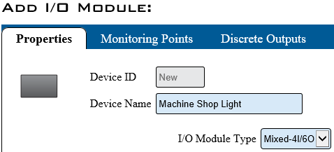
Enter a name for the device - select Mixed 4I/6O for I/O Module Type.
3141 4.png


Step 4.
Select the Discrete Outputs tab.
3141 5.png


Step 5.
Select Discrete Output 1.
3141 7.png


Step 6.
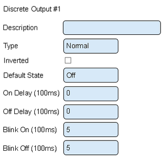
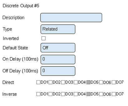
There are 2 Types that apply to a Wireless Light - Normal & Related. Below is a screen shot of each type and a Properties description:
3141 8.png
3141 9.png
Normal Related
Description – enter a name for the output – light color.
Type – there are 3 options available - Disabled, Normal, Related.
Inverted – output will do the opposite of normal.
Default State – what the output will do when no commands/actions have been received.
On Delay – number of milliseconds to elapse before the output turns on.
Off Delay – number of milliseconds to elapse before the output turns off.
Blink On – number of milliseconds to stay on during blink.
Blink Off – number or milliseconds to stay off during blink.
Direct – available when Related Type is selected. Not applicable.
Inverse – available when Related Type is selected. Explained in Step 8.


Step 7.
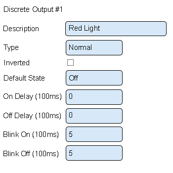
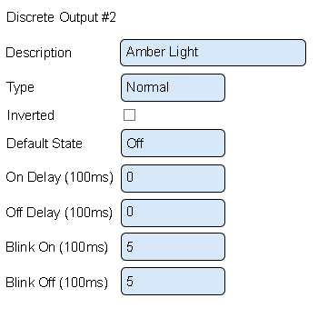
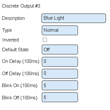
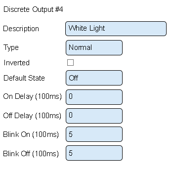
Use the following setup for the Red, Amber, Blue & White lights.
Select the next Discrete Output in the list for each of the other lights.
3141 10.png
3141 11.png
Discrete Output 1 - Red Light Discrete Output 2 - Amber Light
3141 12.png
3141 13.png
Discrete Output 3 - Blue Light Discrete Output 3 - White Light
Description – enter the light color.
Type – leave this as normal.
Inverted – leave this unchecked.
Default State – select Off.
On Delay – enter Zero.
Off Delay – enter Zero.
Blink On – enter 5.
Blink Off – enter 5.


Step 8.
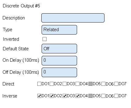
Select Discrete Output 5 from the list - use the setup shown below.
The Green light is setup differently from the other lights. This is done so that the Green light is On when the other lights are Off and Off - then Off other lights are On.
3141 14.png
Discrete Output 5 - Green Light
Description – enter Green light.
Type – select related.
Inverted – leave this unchecked.
On Delay – leave this set to 0.
Off Delay – leave this set to 0.
Direct – leave all unchecked.
Inverse – check mark DO1, DO2, DO3 and DO4.


Step 9.
When all the lights have been added to the configuration - Select Save & Exit.
3141 15.png


Step 10.
The configuration will need to be sent to the device.
CLICK HERE for instructions. The instructions show a PSM - the steps are the same for an IO module.


RelatedHowTos.png
Select a Guide Here
Instructions on Installing a Wireless Light Module
Instructions on Configurating Devices to use a Wireless Light Module


SearchHeader.png


VC Footer.png
Follow Us On LinkedIn View our Blog