Difference between revisions of "VT3000 - Install PSM with IO"
Jump to navigation
Jump to search
SupportAdmin (talk | contribs) |
SupportAdmin (talk | contribs) m (Text replacement - "https://www.linkedin.com/company/versacall-technologies-inc-/mycompany/" to "https://www.linkedin.com/company/versacall/") |
||
| (17 intermediate revisions by the same user not shown) | |||
| Line 1: | Line 1: | ||
=Overview= | {|style="background:transparent; color:black" border="0" height="230" align="center" valign="bottom" | ||
|+style="background:transparent| | |||
|-align="center" | |||
| | |||
== | |[[Image:CallUsBtn.png|Call Now 858-677-6766]] | ||
| | |||
|[[Image:SubmitTckBtn.png|link=https://www.versacall.com/customer-support/service-ticket]] | |||
< | | | ||
File:bscin18.png|Touch Screen | |[[Image:EmailUsBtn.png|link=mailto:[email protected]?Subject=Help%20Needed%20Wiki&body=Type%20Message%20Here]] | ||
File:bscin26.png| | |} | ||
< | <br> | ||
---- | |||
= | ---- | ||
<br> | |||
[[File:GeneralHeader.png]] | |||
<br> | |||
{|style="margin:left; width: 100px; background:#eaf3ff; padding:5px; border:2px solid #000000;" | |||
File: | |- | ||
< | |<big>'''Overview'''</big> | ||
{|style="margin:left; width: 800px; background:#F0F0F0; padding:5px; border:2px solid #000000;" | |||
|valign="top" | | |||
|- | |||
|A PSM Module is made up of a Touch Screen & an I/O Module. Both pieces must have acces to 110VAC power and a mounting location that places them within 15 feet of each other. | |||
|} | |||
File:Install | |} | ||
< | <br> | ||
{|style="margin:left; width: 100px; background:#eaf3ff; padding:5px; border:2px solid #000000;" | |||
|- | |||
|<big>'''Requirements'''</big> | |||
{|style="margin:left; width: 800px; background:#F0F0F0; padding:5px; border:2px solid #000000;" | |||
|valign="top" | | |||
File: | {| class="wikitable mw-collapsible mw-collapsed" width="775px;" | ||
< | |- | ||
|style="text-align: center;" | '''See Requirements Here''' | |||
|- | |||
|'''1.''' The VT3000 Core Software installed and running on your system. | |||
|- | |||
|'''2.''' Coordinator connected and communicating with your VersaCall system. | |||
File:Install PSM4.gif | |- | ||
< | |'''3.''' PSM Module - Touch Screen & I/O Module. | ||
|- | |||
|'''4.''' Two available 110VAC outlets at the PSM mounting location. | |||
|} | |||
|} | |||
|} | |||
File:Install PSM5.gif | <br> | ||
< | {|style="margin:left; width: 100px; background:#eaf3ff; padding:5px; border:2px solid #000000;" | ||
|- | |||
|<big>'''Hardware Components'''</big> | |||
{|style="margin:left; width: 800px; background:#F0F0F0; padding:5px; border:2px solid #000000;" | |||
|valign="top" | | |||
|- | |||
|[[File:bscin18.png|center|200px|Touch Screen]] || [[File:bscin26.png|center|200px|I/O Module]] | |||
File: | |} | ||
|} | |||
< | <br> | ||
---- | |||
---- | |||
<br> | |||
[[File:InstructionHeader.png]] | |||
<br> | |||
File: | {|style="margin:left; width: 100px; background:#eaf3ff; padding:5px; border:2px solid #000000;" | ||
|- | |||
< | |<big>'''Step 1.'''</big> | ||
{|style="margin:left; width: 800px; background:#F0F0F0; padding:5px; border:2px solid #000000;" | |||
|valign="top" | | |||
|- | |||
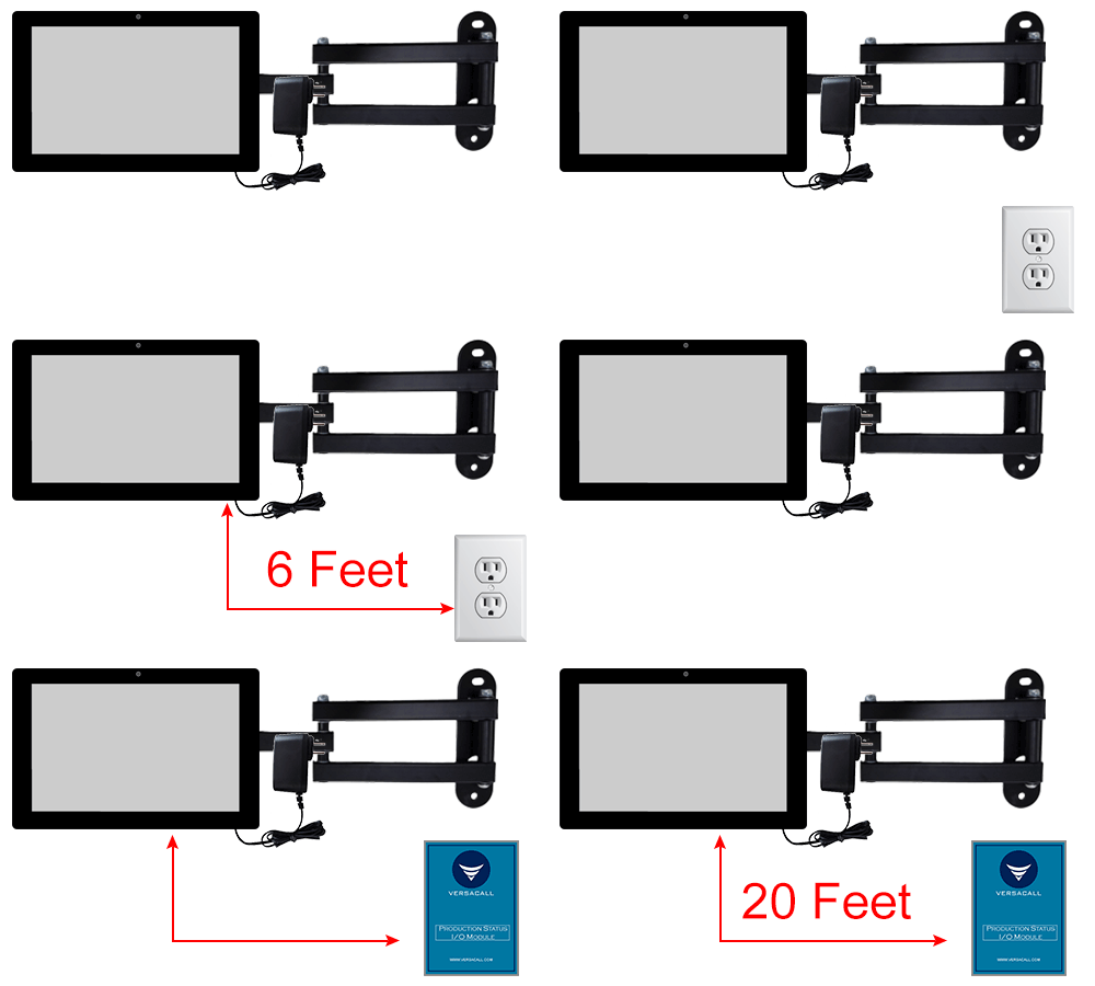
|Mount IO Module within 6 feet of an electrical outlet. | |||
{|style="margin:left;" | |||
File: | |valign="top" | | ||
< | {|class="wikitable" style=" align="center; " background:white;" | ||
|- | |||
|[[File:Install_PSM1.gif]] | |||
|} | |||
|} | |||
|} | |||
File: | |} | ||
< | <br> | ||
---- | |||
<br> | |||
{|style="margin:left; width: 100px; background:#eaf3ff; padding:5px; border:2px solid #000000;" | |||
|- | |||
< | |<big>'''Step 2.'''</big> | ||
{|style="margin:left; width: 800px; background:#F0F0F0; padding:5px; border:2px solid #000000;" | |||
|valign="top" | | |||
|- | |||
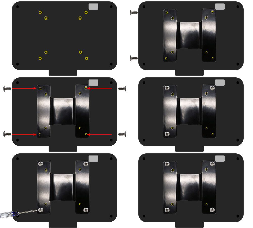
|Attach Touch Screen to the mount using the included screws. | |||
{|style="margin:left;" | |||
|valign="top" | | |||
{|class="wikitable" style="background:white;" | |||
File: | |- | ||
< | |[[File:Install BSCWIO5.gif]] | ||
|} | |||
|} | |||
|} | |||
|} | |||
<br> | |||
File: | ---- | ||
< | <br> | ||
{|style="margin:left; width: 100px; background:#eaf3ff; padding:5px; border:2px solid #000000;" | |||
|- | |||
= | |<big>'''Step 3.'''</big> | ||
{|style="margin:left; width: 800px; background:#F0F0F0; padding:5px; border:2px solid #000000;" | |||
[[ | |valign="top" | | ||
|- | |||
|Mount the Touch Screen within 6 feet of an electrical outlet & within 20 feet of the IO Module. | |||
= | {|style="margin:left;" | ||
|valign="top" | | |||
< | {|class="wikitable" style="background:white;" | ||
File: | |- | ||
< | |[[File:Install_PSM3.gif]] | ||
|} | |||
|} | |||
|} | |||
|} | |||
<br> | |||
---- | |||
<br> | |||
{|style="margin:left; width: 100px; background:#eaf3ff; padding:5px; border:2px solid #000000;" | |||
|- | |||
|<big>'''Step 4.'''</big> | |||
{|style="margin:left; width: 800px; background:#F0F0F0; padding:5px; border:2px solid #000000;" | |||
|valign="top" | | |||
|- | |||
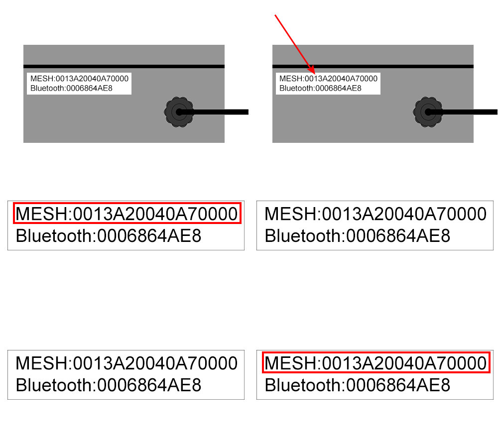
|Find & Note of the Mesh Address on IO Module. - plug in IO Module & the Touch Screen. | |||
{|style="margin:left;" | |||
|valign="top" | | |||
{|class="wikitable" style="background:white;" | |||
|- | |||
|[[File:Install PSM4.gif]] | |||
|} | |||
|} | |||
|} | |||
|} | |||
<br> | |||
---- | |||
<br> | |||
{|style="margin:left; width: 100px; background:#eaf3ff; padding:5px; border:2px solid #000000;" | |||
|- | |||
|<big>'''Step 5.'''</big> | |||
{|style="margin:left; width: 800px; background:#F0F0F0; padding:5px; border:2px solid #000000;" | |||
|valign="top" | | |||
|- | |||
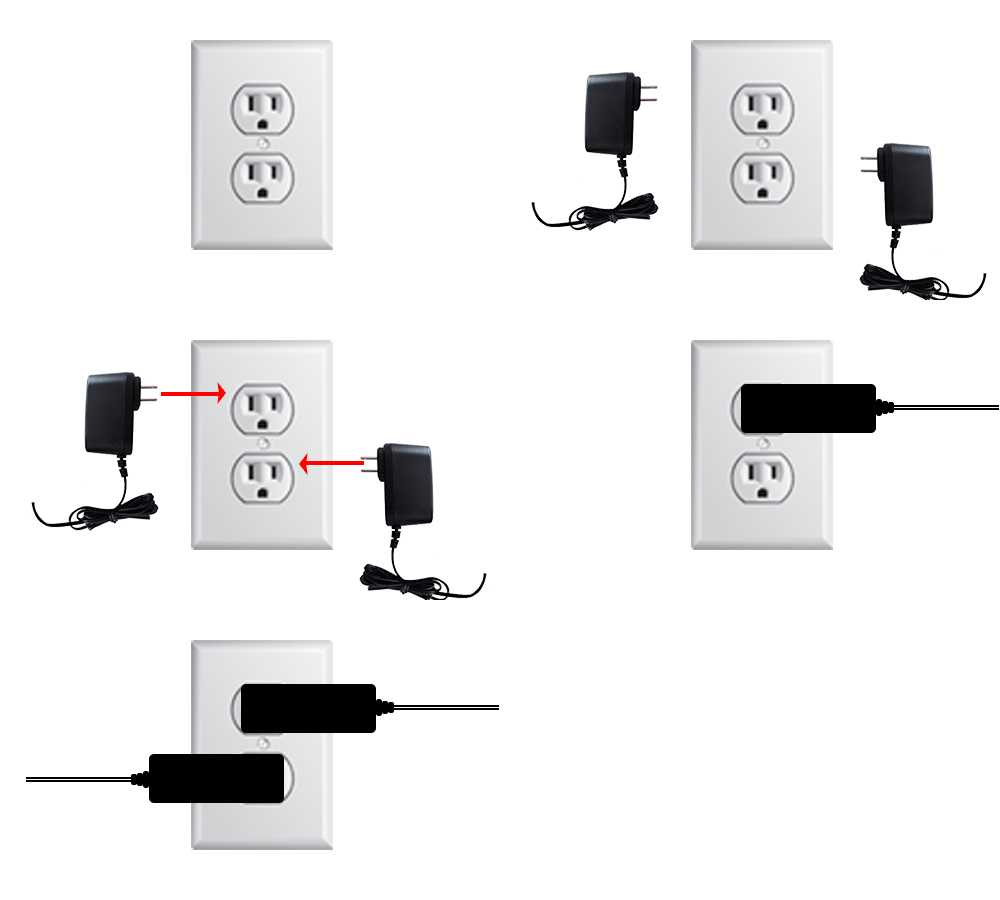
|Plug in the IO Module & Touch Screen power. | |||
{|style="margin:left;" | |||
|valign="top" | | |||
{|class="wikitable" style="background:white;" | |||
|- | |||
|[[File:Install PSM5.gif]] | |||
|} | |||
|} | |||
|} | |||
|} | |||
<br> | |||
---- | |||
<br> | |||
{|style="margin:left; width: 100px; background:#eaf3ff; padding:5px; border:2px solid #000000;" | |||
|- | |||
|<big>'''Step 6.'''</big> | |||
{|style="margin:left; width: 800px; background:#F0F0F0; padding:5px; border:2px solid #000000;" | |||
|valign="top" | | |||
|- | |||
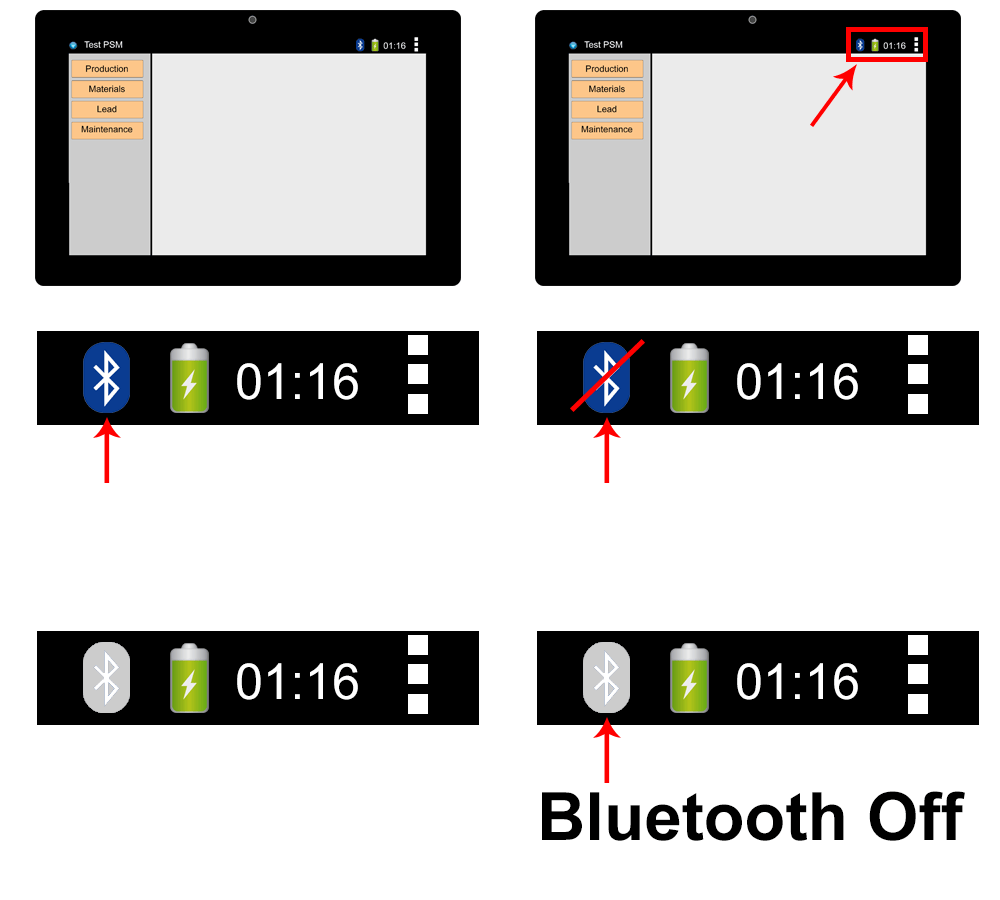
|The IO Module & Touch Screen will automatically connect - verify Bluetooth connection on the Touch Screen. | |||
{|style="margin:left;" | |||
|valign="top" | | |||
{|class="wikitable" style="background:white;" | |||
|- | |||
|[[File:Install PSM6.gif]] | |||
|} | |||
|} | |||
|} | |||
|} | |||
<br> | |||
---- | |||
<br> | |||
{|style="margin:left; width: 100px; background:#eaf3ff; padding:5px; border:2px solid #000000;" | |||
|- | |||
|<big>'''Step 7.'''</big> | |||
{|style="margin:left; width: 800px; background:#F0F0F0; padding:5px; border:2px solid #000000;" | |||
|valign="top" | | |||
|- | |||
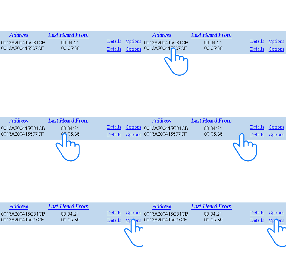
|Open VT3000 Core Software select Diagnostics - select Device Status. | |||
{|style="margin:left;" | |||
|valign="top" | | |||
{|class="wikitable" style="background:white;" | |||
|- | |||
|[[File:Install PSM7.gif]] | |||
|} | |||
|} | |||
|} | |||
|} | |||
<br> | |||
---- | |||
<br> | |||
{|style="margin:left; width: 100px; background:#eaf3ff; padding:5px; border:2px solid #000000;" | |||
|- | |||
|<big>'''Step 8.'''</big> | |||
{|style="margin:left; width: 800px; background:#F0F0F0; padding:5px; border:2px solid #000000;" | |||
|valign="top" | | |||
|- | |||
|Find the IO Mesh Address in the Address field - select Options link on the right. | |||
{|style="margin:left;" | |||
|valign="top" | | |||
{|class="wikitable" style="background:white;" | |||
|- | |||
|[[File:Install PSM8.gif]] | |||
|} | |||
|} | |||
|} | |||
|} | |||
<br> | |||
---- | |||
<br> | |||
{|style="margin:left; width: 100px; background:#eaf3ff; padding:5px; border:2px solid #000000;" | |||
|- | |||
|<big>'''Step 9.'''</big> | |||
{|style="margin:left; width: 800px; background:#F0F0F0; padding:5px; border:2px solid #000000;" | |||
|valign="top" | | |||
|- | |||
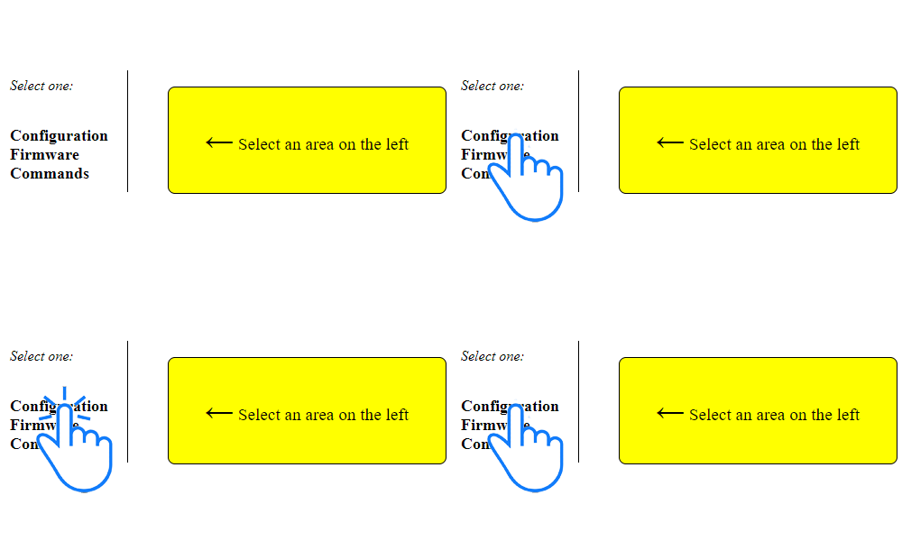
|Select Configuration. | |||
{|style="margin:left;" | |||
|valign="top" | | |||
{|class="wikitable" style="background:white;" | |||
|- | |||
|[[File:Install PSM9.gif]] | |||
|} | |||
|} | |||
|} | |||
|} | |||
<br> | |||
---- | |||
<br> | |||
{|style="margin:left; width: 100px; background:#eaf3ff; padding:5px; border:2px solid #000000;" | |||
|- | |||
|<big>'''Step 10.'''</big> | |||
{|style="margin:left; width: 800px; background:#F0F0F0; padding:5px; border:2px solid #000000;" | |||
|valign="top" | | |||
|- | |||
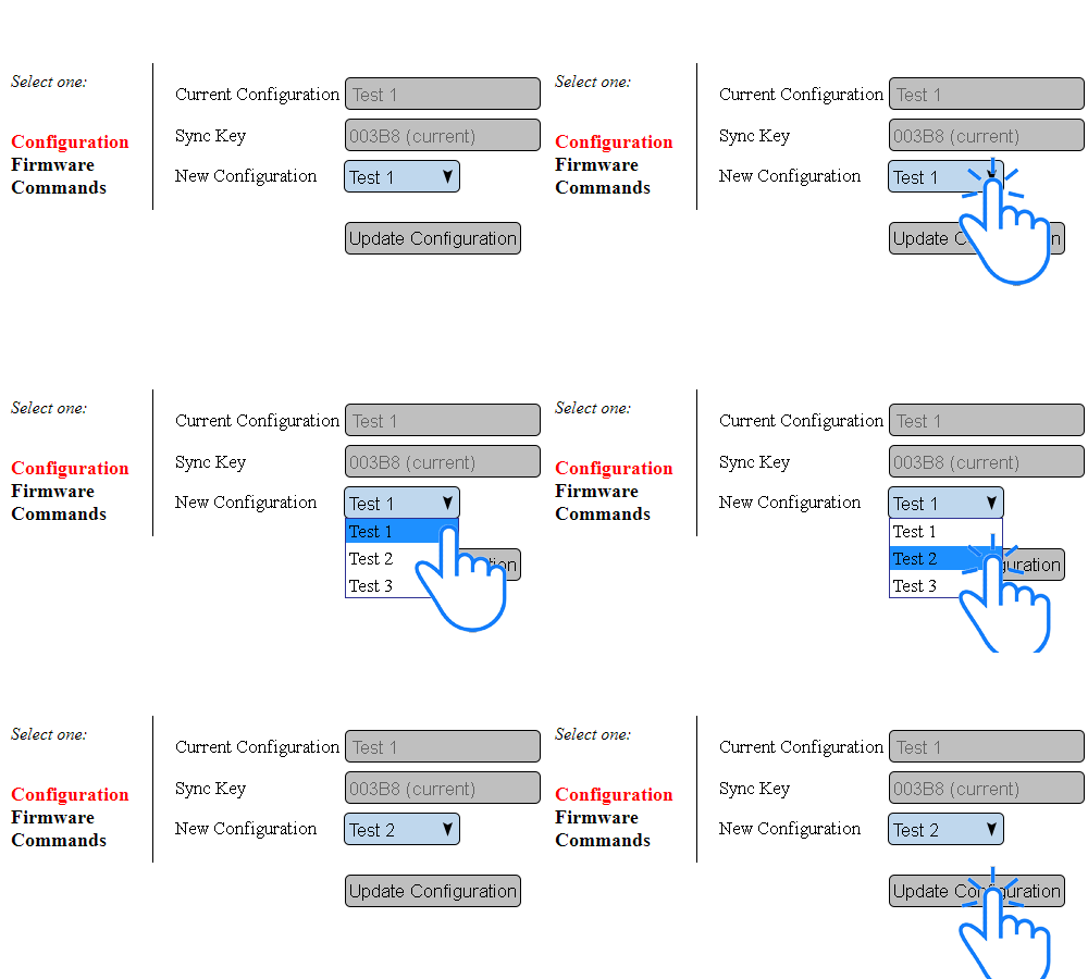
|Select a Device Configuration from the New Configuration field - select Update Configuration button. | |||
{|style="margin:left;" | |||
|valign="top" | | |||
{|class="wikitable" style="background:white;" | |||
|- | |||
|[[File:ConfigMaster1.gif]] | |||
|} | |||
|} | |||
|} | |||
|} | |||
<br> | |||
---- | |||
<br> | |||
{|style="margin:left; width: 100px; background:#eaf3ff; padding:5px; border:2px solid #000000;" | |||
|- | |||
|<big>'''Step 11.'''</big> | |||
{|style="margin:left; width: 800px; background:#F0F0F0; padding:5px; border:2px solid #000000;" | |||
|valign="top" | | |||
|- | |||
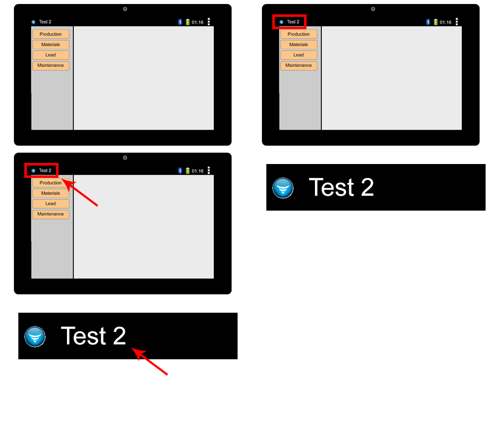
|Go to the Touch Screen - verify the correct module name shows in the top left corner. | |||
{|style="margin:left;" | |||
|valign="top" | | |||
{|class="wikitable" style="background:white;" | |||
|- | |||
|[[File:Install PSM11.gif]] | |||
|} | |||
|} | |||
|} | |||
|} | |||
<br> | |||
---- | |||
---- | |||
<br> | |||
{|style="margin:auto;" | |||
|+ | |||
[[File:RelatedHowTos.png|center]] | |||
|align="center" | | |||
{| class="wikitable mw-collapsible mw-collapsed" width="400px;" | |||
|- | |||
|style="text-align: center;" | '''Select a Guide Here''' | |||
|- | |||
|[[VT3000 - Install Call Station - Battery|Install a Battery Powered Call Station]] | |||
|- | |||
|[[VT3000 - Install Call Station - Powered|Install a Powered Call Station]] | |||
|- | |||
|[[VT3000 - Install BSC with IO|Install a BSC Device]] | |||
|- | |||
|[[VT3000 - Install TIM with IO|Install a TIM Device]] | |||
|} | |||
|} | |||
<br> | |||
---- | |||
<br> | |||
{|style="margin:auto;" | |||
|+ | |||
[[File:SearchHeader.png|center]] | |||
|align="center" | | |||
{|class="wikitable" | |||
|- | |||
|<inputbox>type=search</inputbox> | |||
|} | |||
|} | |||
<br> | |||
---- | |||
<br> | |||
[[File:VC Footer.png|center]] | |||
{|style="background:transparent; color:black" border="0" height="200" align="center" valign="bottom" cellpadding=10px cellspacing=10px | |||
|+style="background:transparent| | |||
|-align="center" | |||
| | |||
|[[File:LinkedIn.png|Follow Us On LinkedIn|link=https://www.linkedin.com/company/versacall/]] | |||
| | |||
|[[File:BlogIcon.png|View our Blog|link=https://www.versacall.com/blog/]] | |||
|} | |||
<br> | |||
[[Category:VT3000 Core Software]] | |||
[[Category:Device Hardware]] | |||
[[Category:PSM]] | |||
Latest revision as of 19:25, 20 April 2023

|

|

|
Overview
|
Requirements
|
| Hardware Components
|
Step 1.
|
Step 2.
|
Step 3.
|
Step 4.
|
Step 5.
|
Step 6.
|
Step 7.
|
Step 8.
|
Step 9.
|
Step 10.
|
Step 11.
|
|
|
|

|


