Difference between revisions of "VT3000 - Replace SD Card - IO Module"
Jump to navigation
Jump to search
SupportAdmin (talk | contribs) |
SupportAdmin (talk | contribs) m (Text replacement - "https://www.linkedin.com/company/versacall-technologies-inc-/mycompany/" to "https://www.linkedin.com/company/versacall/") |
||
| (4 intermediate revisions by the same user not shown) | |||
| Line 1: | Line 1: | ||
=Overview= | {|style="background:transparent; color:black" border="0" height="230" align="center" valign="bottom" | ||
If your BSC, TIM or PSM is showing a red SD Card icon on the Device Status page, you will need to replace the Micro SD Card inside the IO Module. | |+style="background:transparent| | ||
|-align="center" | |||
| | |||
|[[Image:CallUsBtn.png|Call Now 858-677-6766]] | |||
=Requirements= | | | ||
|[[Image:SubmitTckBtn.png|link=https://www.versacall.com/customer-support/service-ticket]] | |||
| | |||
|[[Image:EmailUsBtn.png|link=mailto:[email protected]?Subject=Help%20Needed%20Wiki&body=Type%20Message%20Here]] | |||
|} | |||
<br> | |||
= | ---- | ||
---- | |||
'''1.''' Stop all | <br> | ||
[[File:GeneralHeader.png]] | |||
'''2.''' Disconnect power | <br> | ||
{|style="margin:left; width: 100px; background:#eaf3ff; padding:5px; border:2px solid #000000;" | |||
|- | |||
File:program1.png | |<big>'''Overview'''</big> | ||
< | {|style="margin:left; width: 800px; background:#F0F0F0; padding:5px; border:2px solid #000000;" | ||
|valign="top" | | |||
|- | |||
'''3.''' On the I/O board – locate the Micro SD card in the top right corner. | |If your BSC, TIM or PSM is showing a red SD Card icon on the Device Status page, you will need to replace the Micro SD Card inside the IO Module. You will see this icon [[File:DSIcon7.png]] appear in the "Status" column on the Device Status page. | ||
|} | |||
|} | |||
<br> | |||
{|style="margin:left; width: 100px; background:#eaf3ff; padding:5px; border:2px solid #000000;" | |||
|- | |||
|<big>'''Requirements'''</big> | |||
{|style="margin:left; width: 800px; background:#F0F0F0; padding:5px; border:2px solid #000000;" | |||
|valign="top" | | |||
{| class="wikitable mw-collapsible mw-collapsed" width="775px;" | |||
|- | |||
|style="text-align: center;" | '''See Requirements Here''' | |||
|- | |||
File:3143 | |'''1.''' The VT3000 Core Software installed and running on your system. | ||
|- | |||
|'''2.''' A Coordinator must be setup, powered and communicating with the VT3000 Core Software. | |||
|- | |||
|'''3.''' A BSC, TIM or PSM I/O Module Powered and communicating with the VT3000 Software. | |||
|- | |||
|'''4.''' A New Micro SD Card 4GB or higher capacity. | |||
|- | |||
|'''5.''' A Philips head screwdriver to remove the I/O Module cover. | |||
|} | |||
|} | |||
|} | |||
<br> | |||
---- | |||
---- | |||
<br> | |||
[[File:InstructionHeader.png]] | |||
<br> | |||
{|style="margin:left; width: 100px; background:#eaf3ff; padding:5px; border:2px solid #000000;" | |||
|- | |||
|<big>'''Step 1.'''</big> | |||
{|style="margin:left; width: 800px; background:#F0F0F0; padding:5px; border:2px solid #000000;" | |||
|valign="top" | | |||
|- | |||
|Stop all active Processes, Counts & Alarms on the device. | |||
{|style="margin:left;" | |||
|valign="top" | | |||
{|class="wikitable" style="background:white; align:center;" | |||
|- | |||
|[[VT3000 - Clear a Call in Active Information|'''CLICK HERE''']] for instructions on how to clear Active Monitoring Points. | |||
|} | |||
|} | |||
|} | |||
|} | |||
<br> | |||
---- | |||
<br> | |||
{|style="margin:left; width: 100px; background:#eaf3ff; padding:5px; border:2px solid #000000;" | |||
|- | |||
|<big>'''Step 2.'''</big> | |||
{|style="margin:left; width: 800px; background:#F0F0F0; padding:5px; border:2px solid #000000;" | |||
|valign="top" | | |||
|- | |||
|Disconnect power on the I/O module - loosen the 4 screws on the cover of the I/O module - remove the cover. | |||
{|style="margin:left;" | |||
|valign="top" | | |||
{|class="wikitable" style="background:white;" | |||
|- | |||
|[[File:program1.png|center|275px]] | |||
|} | |||
|} | |||
|} | |||
|} | |||
<br> | |||
---- | |||
<br> | |||
{|style="margin:left; width: 100px; background:#eaf3ff; padding:5px; border:2px solid #000000;" | |||
|- | |||
|<big>'''Step 3.'''</big> | |||
{|style="margin:left; width: 800px; background:#F0F0F0; padding:5px; border:2px solid #000000;" | |||
|valign="top" | | |||
|- | |||
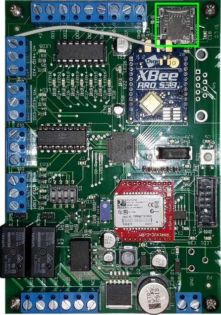
|On the I/O board – locate the Micro SD card in the top right corner of the device. | |||
{|style="margin:left;" | |||
|valign="top" | | |||
{|class="wikitable" style="background:white; align:center;" | |||
|- | |||
|[[File:3143 4.png|center|446px]] | |||
|} | |||
|} | |||
|} | |||
|} | |||
<br> | |||
---- | ---- | ||
<br> | |||
{|style="margin:left; width: 100px; background:#eaf3ff; padding:5px; border:2px solid #000000;" | |||
|- | |||
|<big>'''Step 4.'''</big> | |||
{|style="margin:left; width: 800px; background:#F0F0F0; padding:5px; border:2px solid #000000;" | |||
|valign="top" | | |||
|- | |||
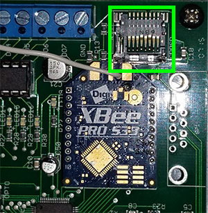
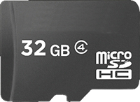
|Remove the micro SD card - push up on the metal sleeve then let it fall back. When you push up the sleeve there will be a click when it is unlocked. '''NOTE:''' do this step with care. If the sleeve is damaged the entire I/O module will need to be replaced. | |||
{|style="margin:left;" | |||
|valign="top" | | |||
{|class="wikitable" style="background:white; align:center; width:775px;" | |||
|- | |||
|[[File:3143 5.png|center|300px]] || [[File:3143 6.png|center|200px]] | |||
|} | |||
|} | |||
|} | |||
|} | |||
<br> | |||
---- | ---- | ||
<br> | |||
{|style="margin:left; width: 100px; background:#eaf3ff; padding:5px; border:2px solid #000000;" | |||
{|style="margin: | |- | ||
|<big>'''Step 5.'''</big> | |||
{|style="margin:left; width: 800px; background:#F0F0F0; padding:5px; border:2px solid #000000;" | |||
|valign="top" | | |valign="top" | | ||
|- | |- | ||
| | |Place the new SD Card into the metal sleeve. Push the sleeve down onto the board. Push the sleeve down towards the bottom of the device to lock it into place. Basically reverse the process in Step #4. | ||
|} | |||
|} | |||
<br> | |||
---- | |||
<br> | |||
{|style="margin:left; width: 100px; background:#eaf3ff; padding:5px; border:2px solid #000000;" | |||
|- | |||
|<big>'''Step 6.'''</big> | |||
{|style="margin:left; width: 800px; background:#F0F0F0; padding:5px; border:2px solid #000000;" | |||
|valign="top" | | |||
|- | |||
|Replace the cover on the device. Hand tighten the 4 screws on the cover - plug in the power cord to an outlet. | |||
{|style="margin:left;" | |||
|valign="top" | | |||
{|class="wikitable" style="background:white;" | |||
|- | |- | ||
|[[ | |[[File:program1.png|center|275px]] | ||
|} | |||
|} | |||
|} | |||
|} | |} | ||
<br> | |||
---- | |||
<br> | |||
{|style="margin:left; width: 100px; background:#eaf3ff; padding:5px; border:2px solid #000000;" | |||
|- | |||
|<big>'''Step 7.'''</big> | |||
{|style="margin:left; width: 800px; background:#F0F0F0; padding:5px; border:2px solid #000000;" | |||
|valign="top" | | |||
|- | |||
|The device will show in the system as Not Configured. Use one of the links below to get instructions on sending a new configuration to the device. | |||
{|style="margin:left;" | |||
|valign="top" | | |valign="top" | | ||
{| class=" | {|class="wikitable" style="background:white; align:center; width:775px;" | ||
|- | |- | ||
|''' | |[[VT3000 - Send a New Configuration to a BSC|'''Click Here''']] for instructions on sending a Configuration to a BSC. | ||
|- | |- | ||
|''' | |[[VT3000 - Send a New Configuration to a TIM or PSM|'''Click Here''']] for instructions on sending a Configuration to a TIM or PSM. | ||
|} | |||
|} | |||
|} | |||
|} | |} | ||
<br> | |||
---- | |||
---- | |||
<br> | |||
{|style="margin:auto;" | |||
|+ | |||
[[File:RelatedHowTos.png|center]] | |||
|align="center" | | |||
{| class="wikitable mw-collapsible mw-collapsed" width="400px;" | |||
|- | |- | ||
| | |style="text-align: center;" | '''Select a Guide Here''' | ||
|- | |||
|[[VT3000_-_Update_Configuration_-_TIM,_PSM,_BSC|Update BSC, TIM or PSM Configuration]] | |||
|- | |||
|[[VT3000_-_Update_Firmware_-_Wireless|Update Firmware Wirelessly]] | |||
|} | |||
|} | |||
<br> | |||
---- | |||
<br> | |||
{|style="margin:auto;" | |||
|+ | |||
[[File:SearchHeader.png|center]] | |||
|align="center" | | |||
{|class="wikitable" | |||
|- | |||
|<inputbox>type=search</inputbox> | |||
|} | |||
|} | |||
<br> | |||
---- | |||
<br> | |||
[[File:VC Footer.png|center]] | |||
{|style="background:transparent; color:black" border="0" height="200" align="center" valign="bottom" cellpadding=10px cellspacing=10px | |||
|+style="background:transparent| | |||
|-align="center" | |||
| | |||
|[[File:LinkedIn.png|Follow Us On LinkedIn|link=https://www.linkedin.com/company/versacall/]] | |||
| | |||
|[[File:BlogIcon.png|View our Blog|link=https://www.versacall.com/blog/]] | |||
|} | |} | ||
<br> | |||
[[Category:VT3000 Core Software]] | [[Category:VT3000 Core Software]] | ||
[[Category:Device Hardware]] | [[Category:Device Hardware]] | ||
Latest revision as of 19:28, 20 April 2023

|

|

|
Requirements
|
Step 1.
|
Step 2.
|
Step 3.
|
Step 4.
|
Step 5.
|
Step 6.
|
Step 7.
|
|
|
|

|


