Difference between revisions of "VT3000 - Install Paging Transmitter - Remote - Different Subnet"
Jump to navigation
Jump to search
SupportAdmin (talk | contribs) m (SupportAdmin moved page VT3000 - Instal Paging Transmitter - Remote - Different Subnet to VT3000 - Install Paging Transmitter - Remote - Different Subnet without leaving a redirect) |
SupportAdmin (talk | contribs) m (Text replacement - "https://www.linkedin.com/company/versacall-technologies-inc-/mycompany/" to "https://www.linkedin.com/company/versacall/") |
||
| (15 intermediate revisions by the same user not shown) | |||
| Line 1: | Line 1: | ||
This guide will show how to configure a remote | {|style="background:transparent; color:black" border="0" height="230" align="center" valign="bottom" | ||
|+style="background:transparent| | |||
|-align="center" | |||
| | |||
|[[Image:CallUsBtn.png|Call Now 858-677-6766]] | |||
| | |||
|[[Image:SubmitTckBtn.png|link=https://www.versacall.com/customer-support/service-ticket]] | |||
| | |||
|[[Image:EmailUsBtn.png|link=mailto:[email protected]?Subject=Help%20Needed%20Wiki&body=Type%20Message%20Here]] | |||
|} | |||
<br> | |||
---- | |||
---- | |||
<br> | |||
[[File:GeneralHeader.png]] | |||
<br> | |||
{|style="margin:left; width: 100px; background:#eaf3ff; padding:5px; border:2px solid #000000;" | |||
|- | |||
|<big>'''Overview'''</big> | |||
{|style="margin:left; width: 800px; background:#F0F0F0; padding:5px; border:2px solid #000000;" | |||
|valign="top" | | |||
|- | |||
|A Paging Transmitter is used to send messages to individual Pagers. This guide will show how to configure a remote transmitter that is on the same subnet as the VersaCall computer/server. IT will need to provide a static IP address that can be used for this device. | |||
|} | |||
|} | |||
<br> | |||
{|style="margin:left; width: 100px; background:#eaf3ff; padding:5px; border:2px solid #000000;" | |||
|- | |||
|<big>'''Requirements'''</big> | |||
{|style="margin:left; width: 800px; background:#F0F0F0; padding:5px; border:2px solid #000000;" | |||
|valign="top" | | |||
{| class="wikitable mw-collapsible mw-collapsed" width="775px;" | |||
|- | |||
|style="text-align: center;" | '''See Requirements Here''' | |||
|- | |||
|'''1.''' The VT3000 Core Software installed and running on your system. | |||
|- | |||
|'''2.''' VersaCall Computer/Server plugged into your network via Ethernet connection. | |||
|- | |||
|'''3.''' New Paging Transmitter & RS-232 hardware. | |||
|- | |||
|'''4.''' The IP Address that the RS-232 is using once it is plugged into power & ethernet port. Your IT Department will need to provide this information by doing a MAC Address search. The MAC Address can be found on the sticker on the bottom of the RS-232 device. | |||
|- | |||
|'''5.''' Static IP, Subnet Mask & Default Gateway from your IT Department. | |||
|- | |||
|'''6.''' Open Ethernet port in the mounting location for the Paging Transmitter. | |||
|- | |||
|'''7.''' Two available 110VAC outlets for power in the mounting location for the Paging Transmitter. | |||
|} | |||
|} | |||
|} | |||
<br> | |||
{|style="margin:left; width: 100px; background:#eaf3ff; padding:5px; border:2px solid #000000;" | |||
|- | |||
|<big>'''Hardware Components'''</big> | |||
{|style="margin:left; width: 800px; background:#F0F0F0; padding:5px; border:2px solid #000000;" | |||
|valign="top" | | |||
|- | |||
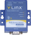
|[[File:trans5.png|center|100px|Paging Transmitter]] || [[File:trans9.png|center|100px|Serial Cable]] || [[File:trans7.png|center|100px|Power Cord]] || [[File:trans6.png|center|20px|Antenna]] || [[File:Coord4.png|center|100px|RS-232]] || [[File:Coord5.png|center|100px|RS-232 Power Cord]] || [[File:Coord6.png|center|100px|Serial Cable]] | |||
|} | |||
|} | |||
<br> | |||
---- | |||
---- | |||
<br> | |||
[[File:InstructionHeader.png]] | |||
<br> | |||
{|style="margin:left; width: 100px; background:#eaf3ff; padding:5px; border:2px solid #000000;" | |||
|- | |||
|<big>'''Step 1.'''</big> | |||
{|style="margin:left; width: 800px; background:#F0F0F0; padding:5px; border:2px solid #000000;" | |||
|valign="top" | | |||
|- | |||
|Connect the Serial Cable to the port on the Transmitter. | |||
{|style="margin:left;" | |||
|valign="top" | | |||
{|class="wikitable" style=" align="center; " background:white;" | |||
|- | |||
|[[File:trans14.png]] | |||
|} | |||
|} | |||
|} | |||
|} | |||
<br> | |||
---- | |||
<br> | |||
{|style="margin:left; width: 100px; background:#eaf3ff; padding:5px; border:2px solid #000000;" | |||
|- | |||
|<big>'''Step 2.'''</big> | |||
{|style="margin:left; width: 800px; background:#F0F0F0; padding:5px; border:2px solid #000000;" | |||
|valign="top" | | |||
|- | |||
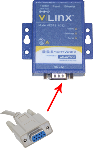
|Connect the other end of the Serial Cable to the RS-232 device. | |||
{|style="margin:left;" | |||
|valign="top" | | |||
{|class="wikitable" style="background:white;" | |||
|- | |||
|[[File:Coord15.png]] | |||
|} | |||
|} | |||
|} | |||
|} | |||
<br> | |||
---- | |||
<br> | |||
{|style="margin:left; width: 100px; background:#eaf3ff; padding:5px; border:2px solid #000000;" | |||
|- | |||
|<big>'''Step 3.'''</big> | |||
{|style="margin:left; width: 800px; background:#F0F0F0; padding:5px; border:2px solid #000000;" | |||
|valign="top" | | |||
|- | |||
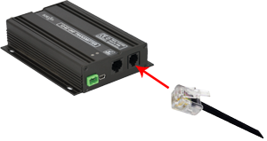
|Connect the Power Cable to the Paging Transmitter. | |||
{|style="margin:left;" | |||
|valign="top" | | |||
{|class="wikitable" style="background:white;" | |||
|- | |||
|[[File:trans1.png]] | |||
|} | |||
|} | |||
|} | |||
|} | |||
<br> | |||
---- | |||
<br> | |||
{|style="margin:left; width: 100px; background:#eaf3ff; padding:5px; border:2px solid #000000;" | |||
|- | |||
|<big>'''Step 4.'''</big> | |||
{|style="margin:left; width: 800px; background:#F0F0F0; padding:5px; border:2px solid #000000;" | |||
|valign="top" | | |||
|- | |||
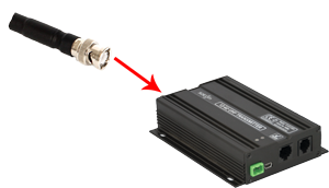
|Connect the Antenna to the Paging Transmitter. | |||
{|style="margin:left;" | |||
|valign="top" | | |||
{|class="wikitable" style="background:white;" | |||
|- | |||
|[[File:trans3.png]] | |||
|} | |||
|} | |||
|} | |||
|} | |||
<br> | |||
---- | |||
<br> | |||
{|style="margin:left; width: 100px; background:#eaf3ff; padding:5px; border:2px solid #000000;" | |||
|- | |||
|<big>'''Step 5.'''</big> | |||
{|style="margin:left; width: 800px; background:#F0F0F0; padding:5px; border:2px solid #000000;" | |||
|valign="top" | | |||
|- | |||
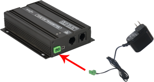
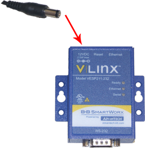
|Connect the Power Cable to the RS-232 device. | |||
{|style="margin:left;" | |||
|valign="top" | | |||
{|class="wikitable" style="background:white;" | |||
|- | |||
|[[File:Coord16.png]] | |||
|} | |||
|} | |||
|} | |||
|} | |||
<br> | |||
---- | |||
<br> | |||
{|style="margin:left; width: 100px; background:#eaf3ff; padding:5px; border:2px solid #000000;" | |||
|- | |||
|<big>'''Step 6.'''</big> | |||
{|style="margin:left; width: 800px; background:#F0F0F0; padding:5px; border:2px solid #000000;" | |||
|valign="top" | | |||
|- | |||
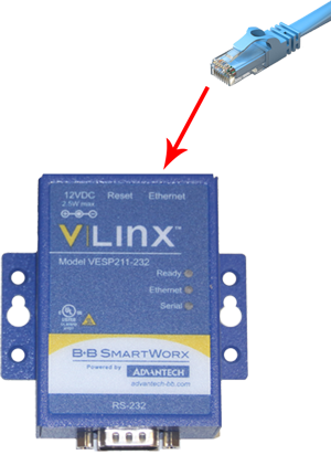
|Connect the Ethernet Cable to the RS-232 device. | |||
{|style="margin:left;" | |||
|valign="top" | | |||
{|class="wikitable" style="background:white;" | |||
|- | |||
|[[File:Coord17.png]] | |||
|} | |||
|} | |||
|} | |||
|} | |||
<br> | |||
---- | |||
<br> | |||
{|style="margin:left; width: 100px; background:#eaf3ff; padding:5px; border:2px solid #000000;" | |||
|- | |||
|<big>'''Step 7.'''</big> | |||
{|style="margin:left; width: 800px; background:#F0F0F0; padding:5px; border:2px solid #000000;" | |||
|valign="top" | | |||
|- | |||
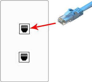
|Connect the Ethernet Cable to your available port. | |||
{|style="margin:left;" | |||
|valign="top" | | |||
{|class="wikitable" style="background:white;" | |||
|- | |||
|[[File:Coord18.png]] | |||
|} | |||
|} | |||
|} | |||
|} | |||
<br> | |||
---- | |||
<br> | |||
{|style="margin:left; width: 100px; background:#eaf3ff; padding:5px; border:2px solid #000000;" | |||
|- | |||
|<big>'''Step 8.'''</big> | |||
{|style="margin:left; width: 800px; background:#F0F0F0; padding:5px; border:2px solid #000000;" | |||
|valign="top" | | |||
|- | |||
|Connect both Power Cables to an Electrical Outlet. | |||
{|style="margin:left;" | |||
|valign="top" | | |||
{|class="wikitable" style="background:white;" | |||
|- | |||
|[[File:bscin4.png]] | |||
|} | |||
|} | |||
|} | |||
|} | |||
<br> | |||
---- | |||
<br> | |||
{|style="margin:left; width: 100px; background:#eaf3ff; padding:5px; border:2px solid #000000;" | |||
|- | |||
|<big>'''Step 9.'''</big> | |||
{|style="margin:left; width: 800px; background:#F0F0F0; padding:5px; border:2px solid #000000;" | |||
|valign="top" | | |||
|- | |||
|Open a web browser (IE, Firefox or Chrome) – enter the IP address for the port the RS-232 device is plugged into or the IP address from the MAC trace. | |||
{|style="margin:left;" | |||
|valign="top" | | |||
{|class="wikitable" style="background:white;" | |||
|- | |||
|[[File:3103_2.png]] | |||
|} | |||
|} | |||
|} | |||
|} | |||
<br> | |||
---- | |||
<br> | |||
{|style="margin:left; width: 100px; background:#eaf3ff; padding:5px; border:2px solid #000000;" | |||
|- | |||
|<big>'''Step 10.'''</big> | |||
{|style="margin:left; width: 800px; background:#F0F0F0; padding:5px; border:2px solid #000000;" | |||
|valign="top" | | |||
|- | |||
|Leave the Password blank – select the Login button. | |||
{|style="margin:left;" | |||
|valign="top" | | |||
{|class="wikitable" style="background:white;" | |||
|- | |||
|[[File:3103_3.png]] | |||
|} | |||
|} | |||
|} | |||
|} | |||
<br> | |||
---- | |||
<br> | |||
{|style="margin:left; width: 100px; background:#eaf3ff; padding:5px; border:2px solid #000000;" | |||
|- | |||
|<big>'''Step 11.'''</big> | |||
{|style="margin:left; width: 800px; background:#F0F0F0; padding:5px; border:2px solid #000000;" | |||
|valign="top" | | |||
|- | |||
|Enter any name to identify the transmitter – select the Next button. | |||
{|style="margin:left;" | |||
|valign="top" | | |||
{|class="wikitable" style="background:white;" | |||
|- | |||
|[[File:3103_4.png]] | |||
|} | |||
|} | |||
|} | |||
|} | |||
<br> | |||
---- | |||
<br> | |||
{|style="margin:left; width: 100px; background:#eaf3ff; padding:5px; border:2px solid #000000;" | |||
|- | |||
|<big>'''Step 12.'''</big> | |||
{|style="margin:left; width: 800px; background:#F0F0F0; padding:5px; border:2px solid #000000;" | |||
|valign="top" | | |||
|- | |||
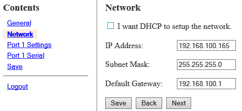
|Enter IP address information provided by your IT department – select the Next button. | |||
{|style="margin:left;" | |||
|valign="top" | | |||
{|class="wikitable" style="background:white;" | |||
|- | |||
|[[File:3103_5.png]] | |||
|} | |||
|} | |||
|} | |||
|} | |||
<br> | |||
---- | |||
<br> | |||
{|style="margin:left; width: 100px; background:#eaf3ff; padding:5px; border:2px solid #000000;" | |||
|- | |||
|<big>'''Step 13.'''</big> | |||
{|style="margin:left; width: 800px; background:#F0F0F0; padding:5px; border:2px solid #000000;" | |||
|valign="top" | | |||
|- | |||
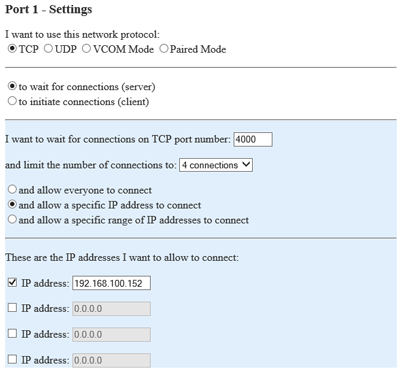
|Use the settings below. | |||
{|style="margin:left;" | |||
|valign="top" | | |||
{|class="wikitable" style="background:white; width:775px;" | |||
|- | |||
|[[File:trans16.png|border|center]] | |||
|} | |||
{|class="wikitable" style="background:white; width:775px;" | |||
|- | |||
|'''Network Protocol''' – select TCP – select “to wait for connections”. | |||
|- | |||
|'''Port Number''' – enter 4000. | |||
|- | |||
|'''Limit''' – select 4 connections from the drop down list. | |||
|- | |||
|'''IP Address''' – enter the IP address of the VersaCall computer. | |||
|- | |||
|style="text-align:center;"|'''NOTE:''' The IP address shown in the image is for reference purposes - use the IP address of your VersaCall computer/server. | |||
|} | |||
|} | |||
|} | |||
|} | |||
<br> | |||
---- | |||
<br> | |||
{|style="margin:left; width: 100px; background:#eaf3ff; padding:5px; border:2px solid #000000;" | |||
|- | |||
|<big>'''Step 14.'''</big> | |||
{|style="margin:left; width: 800px; background:#F0F0F0; padding:5px; border:2px solid #000000;" | |||
|valign="top" | | |||
|- | |||
|Select the Advanced button. | |||
{|style="margin:left;" | |||
|valign="top" | | |||
{|class="wikitable" style="background:white;" | |||
|- | |||
|[[File:3103_7.png]] | |||
|} | |||
|} | |||
|} | |||
|} | |||
<br> | |||
---- | |||
<br> | |||
{|style="margin:left; width: 100px; background:#eaf3ff; padding:5px; border:2px solid #000000;" | |||
|- | |||
|<big>'''Step 15.'''</big> | |||
{|style="margin:left; width: 800px; background:#F0F0F0; padding:5px; border:2px solid #000000;" | |||
|valign="top" | | |||
|- | |||
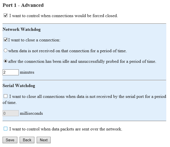
|Use the settings below. | |||
{|style="margin:left;" | |||
|valign="top" | | |||
{|class="wikitable" style="background:white; width:775px;" | |||
|- | |||
|[[File:3103_8.png|border|center]] | |||
|} | |||
{|class="wikitable" style="background:white; width:775px;" | |||
|- | |||
|'''Advanced''' – click in the box next to “I want to control when connections would be forced to close” to place a check mark in it. | |||
|- | |||
|'''Network''' – click in the box next to “I want to close a connection” to place a check mark in it. | |||
|- | |||
|'''After the connection is idle''' - select this option - enter 2 in the minutes field. | |||
|- | |||
|'''Serial''' – uncheck the box and leave the milliseconds field blank. | |||
|- | |||
|'''Data Packets''' – do not select the option to control data packets. | |||
|} | |||
|} | |||
|} | |||
|} | |||
<br> | |||
---- | |||
<br> | |||
{|style="margin:left; width: 100px; background:#eaf3ff; padding:5px; border:2px solid #000000;" | |||
|- | |||
|<big>'''Step 16.'''</big> | |||
{|style="margin:left; width: 800px; background:#F0F0F0; padding:5px; border:2px solid #000000;" | |||
|valign="top" | | |||
|- | |||
|Select the Next button. | |||
{|style="margin:left;" | |||
|valign="top" | | |||
{|class="wikitable" style="background:white;" | |||
|- | |||
|[[File:3103_9.png]] | |||
|} | |||
|} | |||
|} | |||
|} | |||
<br> | |||
---- | |||
<br> | |||
{|style="margin:left; width: 100px; background:#eaf3ff; padding:5px; border:2px solid #000000;" | |||
|- | |||
|<big>'''Step 17.'''</big> | |||
{|style="margin:left; width: 800px; background:#F0F0F0; padding:5px; border:2px solid #000000;" | |||
|valign="top" | | |||
|- | |||
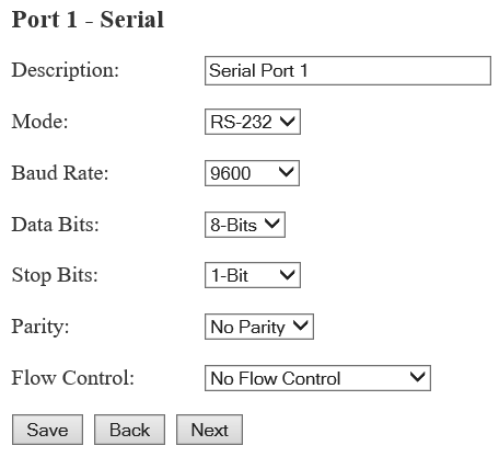
|Use the settings below: | |||
{|style="margin:left;" | |||
|valign="top" | | |||
{|class="wikitable" style="background:white; width:775px;" | |||
|- | |||
|[[File:3103_10.png|border|center]] | |||
|} | |||
{|class="wikitable" style="background:white; width:775px;" | |||
|- | |||
|'''Description''' – enter Serial Port 1 | |||
|- | |||
|'''Mode''' – select RS-232 | |||
|- | |||
|'''Baud Rate''' – select 9600 | |||
|- | |||
|'''Data Bits''' – select 8-Bits | |||
|- | |||
|'''Stop Bits''' – select 1-Bit | |||
|- | |||
|'''Parity''' – select No Parity | |||
|- | |||
|'''Flow Control''' – select No Flow Control | |||
|} | |||
|} | |||
|} | |||
|} | |||
<br> | |||
---- | |||
<br> | |||
{|style="margin:left; width: 100px; background:#eaf3ff; padding:5px; border:2px solid #000000;" | |||
|- | |||
|<big>'''Step 18.'''</big> | |||
{|style="margin:left; width: 800px; background:#F0F0F0; padding:5px; border:2px solid #000000;" | |||
|valign="top" | | |||
|- | |||
|Select the Next button. | |||
{|style="margin:left;" | |||
|valign="top" | | |||
{|class="wikitable" style="background:white;" | |||
|- | |||
|[[File:3103_9.png]] | |||
|} | |||
|} | |||
|} | |||
|} | |||
<br> | |||
---- | |||
<br> | |||
{|style="margin:left; width: 100px; background:#eaf3ff; padding:5px; border:2px solid #000000;" | |||
|- | |||
|<big>'''Step 19.'''</big> | |||
{|style="margin:left; width: 800px; background:#F0F0F0; padding:5px; border:2px solid #000000;" | |||
|valign="top" | | |||
|- | |||
|Select the Save button. | |||
{|style="margin:left;" | |||
|valign="top" | | |||
{|class="wikitable" style="background:white;" | |||
|- | |||
|[[File:3103_11.png]] | |||
|} | |||
|} | |||
|} | |||
|} | |||
<br> | |||
---- | |||
<br> | |||
{|style="margin:left; width: 100px; background:#eaf3ff; padding:5px; border:2px solid #000000;" | |||
|- | |||
|<big>'''Step 20.'''</big> | |||
{|style="margin:left; width: 800px; background:#F0F0F0; padding:5px; border:2px solid #000000;" | |||
|valign="top" | | |||
|- | |||
|Go to the VersaCall Computer - open the VT3000 home page - select Administration – System Settings – Service. | |||
{|style="margin:left;" | |||
|valign="top" | | |||
{|class="wikitable" style="background:white;" | |||
|- | |||
|[[File:HT3100_2.png|center|85px]] || [[File:HT3100_3.png|center|85px]] || [[File:HT3100_4.png|center|85px]] | |||
|} | |||
|} | |||
|} | |||
|} | |||
<br> | |||
---- | |||
<br> | |||
{|style="margin:left; width: 100px; background:#eaf3ff; padding:5px; border:2px solid #000000;" | |||
|- | |||
|<big>'''Step 21.'''</big> | |||
{|style="margin:left; width: 800px; background:#F0F0F0; padding:5px; border:2px solid #000000;" | |||
|valign="top" | | |||
|- | |||
|Select the Paging Transmitter tab – select the add “+” icon. | |||
{|style="margin:left;" | |||
|valign="top" | | |||
{|class="wikitable" style="background:white;" | |||
|- | |||
|[[File:3103_18.png]] | |||
|} | |||
|} | |||
|} | |||
|} | |||
<br> | |||
---- | |||
<br> | |||
{|style="margin:left; width: 100px; background:#eaf3ff; padding:5px; border:2px solid #000000;" | |||
|- | |||
|<big>'''Step 22.'''</big> | |||
{|style="margin:left; width: 800px; background:#F0F0F0; padding:5px; border:2px solid #000000;" | |||
|valign="top" | | |||
|- | |||
|Use the settings below: | |||
{|style="margin:left;" | |||
|valign="top" | | |||
{|class="wikitable" style="background:white; width:775px;" | |||
|- | |||
|[[File:3103_19.png|border|center]] | |||
|} | |||
{|class="wikitable" style="background:white; width:775px;" | |||
|- | |||
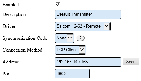
|'''Enabled''' – click on the box to place a check mark – this will enable the device. | |||
|- | |||
|'''Description''' – enter any name for the transmitter. | |||
|- | |||
|'''Driver''' – select the Salcom 12-62 - Remote driver from the list. | |||
|- | |||
|'''Synchronization Code''' – if installing multiple transmitters, use the different codes. | |||
|- | |||
|'''Connection Method''' – select TCP Client from the list. | |||
|- | |||
|'''Address''' – enter the Static IP address that you entered in Step 5. | |||
|- | |||
|'''Port''' – enter 4000. | |||
|} | |||
|} | |||
|} | |||
|} | |||
<br> | |||
---- | |||
<br> | |||
{|style="margin:left; width: 100px; background:#eaf3ff; padding:5px; border:2px solid #000000;" | |||
|- | |||
|<big>'''Step 23.'''</big> | |||
{|style="margin:left; width: 800px; background:#F0F0F0; padding:5px; border:2px solid #000000;" | |||
|valign="top" | | |||
|- | |||
|Click on the Save & Exit button in the top right corner of the screen. | |||
{|style="margin:left;" | |||
|valign="top" | | |||
{|class="wikitable" style="background:white;" | |||
|- | |||
|[[File:3103_20.png]] | |||
|} | |||
|} | |||
|} | |||
|} | |||
<br> | |||
---- | |||
<br> | |||
{|style="margin:left; width: 100px; background:#eaf3ff; padding:5px; border:2px solid #000000;" | |||
|- | |||
|<big>'''Step 24.'''</big> | |||
{|style="margin:left; width: 800px; background:#F0F0F0; padding:5px; border:2px solid #000000;" | |||
|valign="top" | | |||
|- | |||
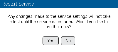
|Select Yes on the Restart warning message. This must be done to complete the setup. | |||
{|style="margin:left;" | |||
|valign="top" | | |||
{|class="wikitable" style="background:white;" | |||
|- | |||
|[[File:3102_22.png]] | |||
|} | |||
|} | |||
|} | |||
|} | |||
<br> | |||
---- | |||
<br> | |||
{|style="margin:left; width: 100px; background:#eaf3ff; padding:5px; border:2px solid #000000;" | |||
|- | |||
|<big>'''Step 25.'''</big> | |||
{|style="margin:left; width: 800px; background:#F0F0F0; padding:5px; border:2px solid #000000;" | |||
|valign="top" | | |||
|- | |||
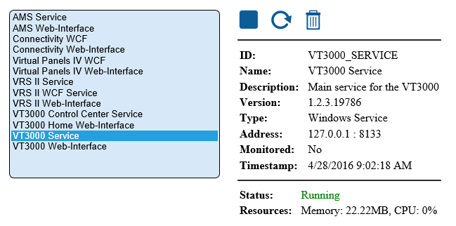
|Restart the VersaCall Service - [[VT3000 - Restart Service|'''Click here for Instructions''']]. | |||
{|style="margin:left;" | |||
|valign="top" | | |||
{|class="wikitable" style="background:white;" | |||
|- | |||
|[[File:3102_25.png]] | |||
|} | |||
|} | |||
|} | |||
|} | |||
<br> | |||
---- | |||
<br> | |||
{|style="margin:left; width: 100px; background:#eaf3ff; padding:5px; border:2px solid #000000;" | |||
|- | |||
|<big>'''Step 26.'''</big> | |||
{|style="margin:left; width: 800px; background:#F0F0F0; padding:5px; border:2px solid #000000;" | |||
|valign="top" | | |||
|- | |||
|Test the Transmitter - [[VT3000_-_Test_-_Pager_Coverage|'''Click here for Instructions''']]. | |||
|} | |||
|} | |||
<br> | |||
---- | |||
---- | |||
<br> | |||
{|style="margin:auto;" | |||
|+ | |||
[[File:RelatedHowTos.png|center]] | |||
|align="center" | | |||
{| class="wikitable mw-collapsible mw-collapsed" width="400px;" | |||
|- | |||
|style="text-align: center;" | '''Select a Guide Here''' | |||
|- | |||
|[[VT3000 - Find Paging Transmitter Settings|Find the Paging Transmitter Properties/Settings]] | |||
|- | |||
[[ | |[[VT3000 - Install Paging Transmitter - USB|Install a USB Paging Transmitter]] | ||
|- | |||
|[[VT3000 - Replace Paging Transmitter - USB|Replace an Existing USB Paging Transmitter]] | |||
|- | |||
|[[VT3000 - Install Paging Transmitter - Remote - Same Subnet|Install a Remote Paging Transmitter on the Same Subnet]] | |||
[[ | |- | ||
|[[VT3000 - Test - Pager Coverage| Test Paging Transmitter Coverage]] | |||
|- | |||
|[[VT3000 - Program a Pager - Capcode|Programming a New Capcode on a Pager]] | |||
|- | |||
[[ | |[[VT3000 - Add Pager|Add a Pager to Output in VT3000 Core Software]] | ||
|} | |||
|} | |||
<br> | |||
---- | |||
<br> | |||
{|style="margin:auto;" | |||
|+ | |||
[[File:SearchHeader.png|center]] | |||
|align="center" | | |||
[[ | {|class="wikitable" | ||
|- | |||
|<inputbox>type=search</inputbox> | |||
|} | |||
|} | |||
[[ | <br> | ||
---- | |||
<br> | |||
[[File:VC Footer.png|center]] | |||
{|style="background:transparent; color:black" border="0" height="200" align="center" valign="bottom" cellpadding=10px cellspacing=10px | |||
|+style="background:transparent| | |||
|-align="center" | |||
| | |||
|[[File:LinkedIn.png|Follow Us On LinkedIn|link=https://www.linkedin.com/company/versacall/]] | |||
| | |||
|[[File:BlogIcon.png|View our Blog|link=https://www.versacall.com/blog/]] | |||
|} | |||
<br> | |||
[[Category:VT3000 Core Software]] | |||
[[ | [[Category:System Hardware]] | ||
[[Category:Paging Transmitter - Pagers]] | |||
[[File: | |||
[[File: | |||
[[File: | |||
[[File: | |||
[[ | |||
[[ | |||
[[ | |||
Latest revision as of 19:24, 20 April 2023

|

|

|
Overview
|
Requirements
|
| Hardware Components
|
Step 1.
|
Step 2.
|
Step 3.
|
Step 4.
|
Step 5.
|
Step 6.
|
Step 7.
|
Step 8.
|
Step 9.
|
Step 10.
|
Step 11.
|
Step 12.
|
Step 13.
|
Step 14.
|
Step 15.
|
Step 16.
|
Step 17.
|
Step 18.
|
Step 19.
|
Step 20.
|
Step 21.
|
Step 22.
|
Step 23.
|
Step 24.
|
Step 25.
|
Step 26.
|
|
|

|


