Difference between revisions of "VT3000 - Find Coordinator Settings"
Jump to navigation
Jump to search
SupportAdmin (talk | contribs) |
SupportAdmin (talk | contribs) |
||
| (9 intermediate revisions by the same user not shown) | |||
| Line 1: | Line 1: | ||
=Overview= | {|style="background:transparent; color:black" border="0" height="230" align="center" valign="bottom" | ||
If you have a need to check the Coordinator settings or if a VersaCall Technician asks you provide the settings, the instructions below will show you have to find them. | |+style="background:transparent| | ||
|-align="center" | |||
| | |||
=Requirements= | |[[Image:CallUsBtn.png|Call Now 858-677-6766]] | ||
| | |||
'''1.''' VT3000 Core Software installed and running on your system. | |[[Image:SubmitTckBtn.png|link=https://www.versacall.com/customer-support/service-ticket]] | ||
| | |||
'''2.''' A | |[[Image:EmailUsBtn.png|link=mailto:[email protected]?Subject=Help%20Needed%20Wiki&body=Type%20Message%20Here]] | ||
|} | |||
<br> | |||
---- | |||
---- | |||
<br> | |||
[[File:GeneralHeader.png]] | |||
< | <br> | ||
File: | {|style="margin:left; width: 100px; background:#eaf3ff; padding:5px; border:2px solid #000000;" | ||
|- | |||
|<big>'''Overview'''</big> | |||
< | {|style="margin:left; width: 800px; background:#F0F0F0; padding:5px; border:2px solid #000000;" | ||
|valign="top" | | |||
|- | |||
''' | |If you have a need to check the Coordinator settings or if a VersaCall Technician asks you provide the settings, the instructions below will show you have to find them. | ||
|} | |||
|} | |||
File: | <br> | ||
< | {|style="margin:left; width: 100px; background:#eaf3ff; padding:5px; border:2px solid #000000;" | ||
|- | |||
|<big>'''Requirements'''</big> | |||
{|style="margin:left; width: 800px; background:#F0F0F0; padding:5px; border:2px solid #000000;" | |||
|valign="top" | | |||
< | {| class="wikitable mw-collapsible mw-collapsed" width="775px;" | ||
File: | |- | ||
< | |style="text-align: center;" | '''See Requirements Here''' | ||
|- | |||
|'''1.''' The VT3000 Core Software installed and running on your system. | |||
''' | |- | ||
|'''2.''' A Coordinator must be setup, powered and communicating with the VT3000 Core Software. | |||
|} | |||
File: | |} | ||
|} | |||
<br> | |||
---- | |||
---- | |||
<br> | |||
[[File:VideoHeader.png]] | |||
<br> | |||
{|style="margin:left; width: 100px; background:#eaf3ff; padding:5px; border:2px solid #000000;" | |||
|- | |||
|<big>'''Video'''</big> | |||
{|style="margin:left; width: 800px; background:#F0F0F0; padding:5px; border:2px solid #000000;" | |||
|valign="top" | | |||
File: | |- | ||
< | |[[File:Coord Settings.mkv|center|775px]] | ||
|} | |||
|} | |||
<br> | |||
---- | |||
---- | |||
<br> | |||
[[File:InstructionHeader.png]] | |||
<br> | |||
{|style="margin:left; width: 100px; background:#eaf3ff; padding:5px; border:2px solid #000000;" | |||
|- | |||
|<big>'''Step 1.'''</big> | |||
{|style="margin:left; width: 800px; background:#F0F0F0; padding:5px; border:2px solid #000000;" | |||
|valign="top" | | |||
|- | |||
|Open the VT3000 web interface – select VT3000 Core Software - log in – select Administration – select System Settings - select Service. | |||
{|style="margin:left;" | |||
|valign="top" | | |||
{|class="wikitable" style="background:white; align:center;" | |||
|- | |||
|[[File:HT3100_2.png|center|85px]] || [[File:HT3100_3.png|center|85px]] || [[File:HT3100_4.png|center|85px]] | |||
|- | |||
|style="text-align:center" | '''Administration''' ||style="text-align:center" | '''System Settings''' ||style="text-align:center" | '''Service''' | |||
|} | |||
|} | |||
|} | |||
|} | |||
<br> | |||
---- | |||
<br> | |||
{|style="margin:left; width: 100px; background:#eaf3ff; padding:5px; border:2px solid #000000;" | |||
|- | |||
|<big>'''Step 2.'''</big> | |||
{|style="margin:left; width: 800px; background:#F0F0F0; padding:5px; border:2px solid #000000;" | |||
|valign="top" | | |||
|- | |||
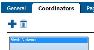
|Select the Coordinators tab. | |||
{|style="margin:left;" | |||
|valign="top" | | |||
{|class="wikitable" style="background:white;" | |||
|- | |||
|[[File:3121_11.png|center|533px]] | |||
|} | |||
|} | |||
|} | |||
|} | |||
<br> | |||
---- | |||
<br> | |||
{|style="margin:left; width: 100px; background:#eaf3ff; padding:5px; border:2px solid #000000;" | |||
|- | |||
|<big>'''Step 3.'''</big> | |||
{|style="margin:left; width: 800px; background:#F0F0F0; padding:5px; border:2px solid #000000;" | |||
|valign="top" | | |||
|- | |||
|Select your Coordinator from the list so that it is highlighted. | |||
{|style="margin:left;" | |||
|valign="top" | | |||
{|class="wikitable" style="background:white; align:center;" | |||
|- | |||
|[[File:Coordinator22.png|center|307px]] | |||
|} | |||
|} | |||
|} | |||
|} | |||
<br> | |||
---- | ---- | ||
{|style="margin: | <br> | ||
{|style="margin:left; width: 100px; background:#eaf3ff; padding:5px; border:2px solid #000000;" | |||
|- | |||
|<big>'''Step 4.'''</big> | |||
{|style="margin:left; width: 800px; background:#F0F0F0; padding:5px; border:2px solid #000000;" | |||
|valign="top" | | |||
|- | |||
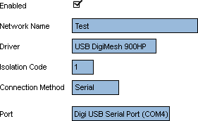
|On the right side of the list you will see these settings for a '''USB Coordinator''': | |||
{|style="margin:left;" | |||
|valign="top" | | |valign="top" | | ||
{| class=" | {|class="wikitable" style="background:white; align:center; width:775px;" | ||
|- | |||
|[[File:3121_13.png|border|center|281px]] | |||
|} | |||
{|class="wikitable" style="background:white; align:center; width:775px;" | |||
|- | |||
|'''Enabled –''' will be check marked to enable the device. | |||
|- | |- | ||
| | |'''Network Name –''' Coordinator Name. | ||
|- | |- | ||
| | |'''Driver –''' USB Digi Mesh 900HP. | ||
|- | |- | ||
| | |'''Isolation Code –''' this is set to 1 unless VersaCall instructs you to change it. | ||
|- | |- | ||
| | |'''Port –''' will show as USB Serial Port (COM#). The COM number will differ from the screen shot in most cases. | ||
|} | |||
|} | |||
|} | |||
|} | |||
<br> | |||
---- | |||
<br> | |||
{|style="margin:left; width: 100px; background:#eaf3ff; padding:5px; border:2px solid #000000;" | |||
|- | |- | ||
| | |<big>'''Step 5.'''</big> | ||
{|style="margin:left; width: 800px; background:#F0F0F0; padding:5px; border:2px solid #000000;" | |||
|valign="top" | | |||
|- | |- | ||
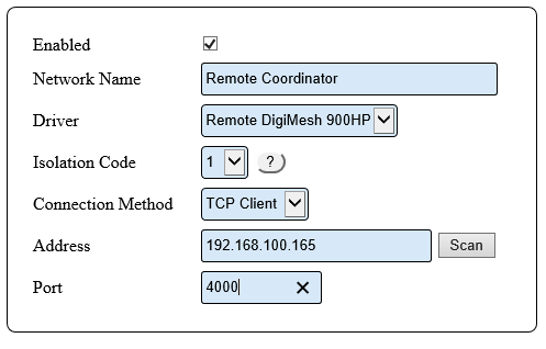
| | |On the right side of the list you will see these settings for a '''Remote Coordinator''': | ||
{|style="margin:left;" | |||
|valign="top" | | |||
{|class="wikitable" style="background:white; align:center; width:775px;" | |||
|- | |- | ||
|[[ | |[[File:HT3101 18.png|center|497px]] | ||
|} | |||
{|class="wikitable" style="background:white; align:center; width:775px;" | |||
|- | |- | ||
| | |'''Enabled –''' will be check marked to enable the device. | ||
|- | |- | ||
| | |'''Network Name –''' Coordinator Name. | ||
|- | |- | ||
| | |'''Driver –''' will be Remote DigiMesh 900HP. | ||
|- | |- | ||
| | |'''Isolation Code –''' leave this set to 1 unless VersaCall instructs you to change it. | ||
|- | |- | ||
| | |'''Connection Method - ''' will be TCP Client. | ||
|- | |||
|'''Address - ''' will have the Static IP address of the RS-232 device. | |||
|- | |||
|'''Port –''' will be set to 4000. | |||
|} | |||
|} | |||
|} | |} | ||
|} | |||
<br> | |||
---- | |||
<br> | |||
{|style="margin:left; width: 100px; background:#eaf3ff; padding:5px; border:2px solid #000000;" | |||
|- | |||
|<big>'''Step 6.'''</big> | |||
{|style="margin:left; width: 800px; background:#F0F0F0; padding:5px; border:2px solid #000000;" | |||
|valign="top" | | |valign="top" | | ||
|- | |- | ||
|''' | |Select the Discard & Exit button to exit the tab/page. | ||
|} | |||
|} | |||
<br> | |||
---- | |||
---- | |||
<br> | |||
{|style="margin:auto;" | |||
|+ | |||
[[File:RelatedHowTos.png|center]] | |||
|align="center" | | |||
{| class="wikitable mw-collapsible mw-collapsed" width="400px;" | |||
|- | |||
|style="text-align: center;" | '''Select a Guide Here''' | |||
|- | |||
|[[VT3000 - Install Coordinator - USB|Install a USB Coordinator]] | |||
|- | |- | ||
| | |[[VT3000 - Replace Coordinator - USB|Replace a USB Coordinator]] | ||
|- | |||
|[[VT3000 - Install Coordinator - Remote - Same Subnet|Install a Remote Coordinator on the Same Subnet as the VersaCall Computer/Server]] | |||
|- | |||
|[[VT3000 - Install Coordinator - Remote - Different Subnet|Install a Remote Coordinator on a Different Subnet than the VersaCall Computer/Server]] | |||
|- | |||
|[[VT3000 - Install Coordinator - Real-Port - Same Subnet|Install a Real-Port Coordinator on the Same Subnet as the VersaCall Computer/Server]] | |||
|- | |||
|[[VT3000 - Install Coordinator - Real-Port - Different Subnet|Install a Real-Port Coordinator on a Different Subnet than the VersaCall Computer/Server]] | |||
|- | |||
|[[VT3000 - Change System (ISO) Isolation Code|Change System ISO Code]] | |||
|} | |} | ||
|} | |} | ||
<br> | |||
---- | ---- | ||
<br> | |||
{|style="margin:auto;" | {|style="margin:auto;" | ||
|+ | |||
[[File:SearchHeader.png|center]] | |||
|align="center" | | |align="center" | | ||
{|class="wikitable" | {|class="wikitable" | ||
|- | |- | ||
|<inputbox>type=search</inputbox> | |<inputbox>type=search</inputbox> | ||
|} | |} | ||
|} | |||
<br> | |||
---- | ---- | ||
<br> | |||
[[File:VC Footer.png|center]] | |||
{|style="background:transparent; color:black" border="0" height="200" align="center" valign="bottom" cellpadding=10px cellspacing=10px | |||
|+style="background:transparent| | |||
|-align="center" | |||
| | |||
|[[File:LinkedIn.png|Follow Us On LinkedIn|link=https://www.linkedin.com/company/versacall/]] | |||
| | |||
|[[File:BlogIcon.png|View our Blog|link=https://www.versacall.com/blog/]] | |||
|} | |||
<br> | |||
[[Category:VT3000 Core Software]] | [[Category:VT3000 Core Software]] | ||
[[Category:System Hardware]] | [[Category:System Hardware]] | ||
[[Category:System Settings]] | [[Category:System Settings]] | ||
[[Category:Coordinator]] | [[Category:Coordinator]] | ||
Latest revision as of 21:28, 19 May 2023

|

|

|
Overview
|
Requirements
|
| Video
|
Step 1.
|
Step 2.
|
Step 3.
|
Step 4.
|
Step 5.
|
Step 6.
|
|
|

|


