Difference between revisions of "VT3000 - Add a Count to a PC Input Module"
Jump to navigation
Jump to search
SupportAdmin (talk | contribs) |
SupportAdmin (talk | contribs) |
||
| Line 1: | Line 1: | ||
{|style="margin:left;" | {|style="margin:left;" | ||
|valign="top" | | |valign="top" | | ||
{|class="wikitable" style="background:#eaf3ff;" | {|class="wikitable" style="background:#eaf3ff; width: 800px;" | ||
|- | |- | ||
!style="text-align: left;"|<big>'''Overview'''</big> | !style="text-align: left;"|<big>'''Overview'''</big> | ||
| Line 18: | Line 18: | ||
|} | |} | ||
|} | |} | ||
<br> | |||
=Instructions | =<big>'''Instructions'''</big>= | ||
<br> | |||
'''1.''' Open the VT3000 web interface – select Configuration – select Devices. | {|style="margin:left; width: 100px; background:#eaf3ff; padding:5px; border:2px solid #000000;" | ||
|- | |||
|<big>'''Step 1.'''</big> | |||
File: | {|style="margin:left; width: 800px; background:#F0F0F0; padding:5px; border:2px solid #000000;" | ||
File: | |valign="top" | | ||
< | |- | ||
|Open the VT3000 web interface – select VT3000 Core Software - log in – select Configuration – select Devices. | |||
{|style="margin:left;" | |||
'''2.''' Select PC Input from the | |valign="top" | | ||
{|class="wikitable" style=" align="center; " background:white;" | |||
|- | |||
File: | |[[File:3110_1.png|center|93px]] || [[File:3139 2.png|center|93px]] | ||
< | |- | ||
|style="text-align:center" | '''Configuration''' ||style="text-align:center" | '''Devices''' | |||
|} | |||
'''3.''' Select the Virtual Inputs tab. | |} | ||
|} | |||
|} | |||
File: | <br> | ||
< | ---- | ||
<br> | |||
{|style="margin:left; width: 100px; background:#eaf3ff; padding:5px; border:2px solid #000000;" | |||
'''4.''' Select the Plus icon from the tool box | |- | ||
|<big>'''Step 2.'''</big> | |||
{|style="margin:left; width: 800px; background:#F0F0F0; padding:5px; border:2px solid #000000;" | |||
File:VCount2.png | |valign="top" | | ||
< | |- | ||
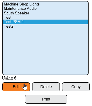
|Select the PC Input Module that you want to add the Count Button to from the list - select the Edit button. | |||
{|style="margin:left;" | |||
'''5.''' Enter Count for the Description | |valign="top" | | ||
{|class="wikitable" style=" align="center; " background:white;" | |||
|- | |||
File:VCount3.png | |[[File:3139 4.png|center|320px]] | ||
< | |} | ||
|} | |||
|} | |||
'''6.''' Select | |} | ||
<br> | |||
---- | |||
File: | <br> | ||
< | {|style="margin:left; width: 100px; background:#eaf3ff; padding:5px; border:2px solid #000000;" | ||
|- | |||
|<big>'''Step 3.'''</big> | |||
= | {|style="margin:left; width: 800px; background:#F0F0F0; padding:5px; border:2px solid #000000;" | ||
|valign="top" | | |||
''' | |- | ||
|Select the Virtual Inputs tab. | |||
{|style="margin:left;" | |||
''' | |valign="top" | | ||
{|class="wikitable" style="background:white;" | |||
|- | |||
File:CountPSM5.png | |[[File:VCount1.png|center|367px]] | ||
< | |} | ||
|} | |||
|} | |||
''' | |} | ||
<br> | |||
---- | |||
File:CountPSM6.png | <br> | ||
< | {|style="margin:left; width: 100px; background:#eaf3ff; padding:5px; border:2px solid #000000;" | ||
|- | |||
|<big>'''Step 4.'''</big> | |||
''' | {|style="margin:left; width: 800px; background:#F0F0F0; padding:5px; border:2px solid #000000;" | ||
|valign="top" | | |||
|- | |||
File:VCount5.png | |Select the Add Input (Plus) icon from the tool box. | ||
< | {|style="margin:left;" | ||
|valign="top" | | |||
{|class="wikitable" style="background:white;" | |||
''' | |- | ||
|[[File:VCount2.png|center|228px]] | |||
|} | |||
File:CountPSM7.png | |} | ||
|} | |||
|} | |||
<br> | |||
---- | |||
<br> | |||
{|style="margin:left; width: 100px; background:#eaf3ff; padding:5px; border:2px solid #000000;" | |||
|- | |||
|<big>'''Step 5.'''</big> | |||
{|style="margin:left; width: 800px; background:#F0F0F0; padding:5px; border:2px solid #000000;" | |||
|valign="top" | | |||
''' | |- | ||
|Virtual Input Properties - Enter Count for the Description - select Count for the Type - ensure Enabled is check marked. | |||
{|style="margin:left;" | |||
File:CountPSM8.png | |valign="top" | | ||
< | {|class="wikitable" style="background:white; width:" | ||
|- | |||
|[[File:VCount3.png|center|292px]] | |||
''' | |} | ||
|} | |||
|} | |||
File: | |} | ||
< | <br> | ||
---- | |||
<br> | |||
''' | {|style="margin:left; width: 100px; background:#eaf3ff; padding:5px; border:2px solid #000000;" | ||
|- | |||
|<big>'''Step 6.'''</big> | |||
File: | {|style="margin:left; width: 800px; background:#F0F0F0; padding:5px; border:2px solid #000000;" | ||
|valign="top" | | |||
|- | |||
|Select Save & Exit button. | |||
''' | {|style="margin:left;" | ||
|valign="top" | | |||
{|class="wikitable" style="background:white;" | |||
|- | |||
< | |[[File:3139 11.png|center|250px]] | ||
|} | |||
|} | |||
|} | |||
|} | |||
<br> | |||
---- | |||
<br> | |||
{|style="margin:left; width: 100px; background:#eaf3ff; padding:5px; border:2px solid #000000;" | |||
|- | |||
|<big>'''Step 7.'''</big> | |||
{|style="margin:left; width: 800px; background:#F0F0F0; padding:5px; border:2px solid #000000;" | |||
|valign="top" | | |||
|- | |||
|Select the PC Input Module that you setup the Virtual Input on in the Steps above - select the Edit button. | |||
{|style="margin:left;" | |||
|valign="top" | | |||
{|class="wikitable" style=" align="center; " background:white;" | |||
|- | |||
||[[File:3139 4.png|center|320px]] | |||
|} | |||
|} | |||
|} | |||
|} | |||
<br> | |||
---- | |||
<br> | |||
{|style="margin:left; width: 100px; background:#eaf3ff; padding:5px; border:2px solid #000000;" | |||
|- | |||
|<big>'''Step 8.'''</big> | |||
{|style="margin:left; width: 800px; background:#F0F0F0; padding:5px; border:2px solid #000000;" | |||
|valign="top" | | |||
|- | |||
|Select the Monitoring Points tab. | |||
{|style="margin:left;" | |||
|valign="top" | | |||
{|class="wikitable" style="background:white;" | |||
|- | |||
|[[File:Reason1.png|center|325px]] | |||
|} | |||
|} | |||
|} | |||
|} | |||
<br> | |||
---- | |||
<br> | |||
{|style="margin:left; width: 100px; background:#eaf3ff; padding:5px; border:2px solid #000000;" | |||
|- | |||
|<big>'''Step 9.'''</big> | |||
{|style="margin:left; width: 800px; background:#F0F0F0; padding:5px; border:2px solid #000000;" | |||
|valign="top" | | |||
|- | |||
|Select the Add Process icon under the Monitoring Points tab if a process does not already exist. | |||
{|style="margin:left;" | |||
|valign="top" | | |||
{|class="wikitable" style=" align="center; " background:white;" | |||
|- | |||
|[[File:CountPSM5.png|center|413px]] | |||
|} | |||
|} | |||
|} | |||
|} | |||
<br> | |||
---- | |||
<br> | |||
{|style="margin:left; width: 100px; background:#eaf3ff; padding:5px; border:2px solid #000000;" | |||
|- | |||
|<big>'''Step 10.'''</big> | |||
{|style="margin:left; width: 800px; background:#F0F0F0; padding:5px; border:2px solid #000000;" | |||
|valign="top" | | |||
|- | |||
|Process Properties - setup the monitoring point as shown below: | |||
{|style="margin:left;" | |||
|valign="top" | | |||
{|class="wikitable" style="background:white; width: 775px;" | |||
|- | |||
|[[File:CountPSM6.png|center|461px]] | |||
|} | |||
{|class="wikitable" style="background:white; width: 775px;" | |||
|- | |||
|'''Process Name''' - enter Work. | |||
|- | |||
|'''Mode''' - select Process. | |||
|} | |||
|} | |||
|} | |||
|} | |||
<br> | |||
---- | |||
<br> | |||
{|style="margin:left; width: 100px; background:#eaf3ff; padding:5px; border:2px solid #000000;" | |||
|- | |||
|<big>'''Step 11.'''</big> | |||
{|style="margin:left; width: 800px; background:#F0F0F0; padding:5px; border:2px solid #000000;" | |||
|valign="top" | | |||
|- | |||
|With the Process Selected in the root - select the Add Sampler icon from the toolbox. | |||
{|style="margin:left;" | |||
|valign="top" | | |||
{|class="wikitable" style=" align="center; " background:white;" | |||
|- | |||
|[[File:VCount5.png|center|321px]] | |||
|} | |||
|} | |||
|} | |||
|} | |||
<br> | |||
---- | |||
<br> | |||
{|style="margin:left; width: 100px; background:#eaf3ff; padding:5px; border:2px solid #000000;" | |||
|- | |||
|<big>'''Step 12.'''</big> | |||
{|style="margin:left; width: 800px; background:#F0F0F0; padding:5px; border:2px solid #000000;" | |||
|valign="top" | | |||
|- | |||
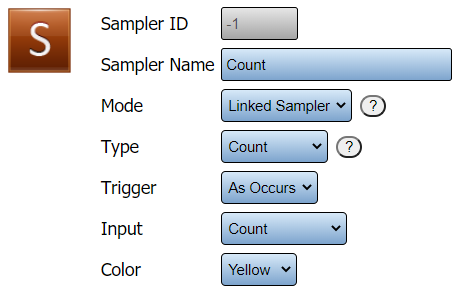
|Sampler Properties - setup the monitoring point as shown below: | |||
{|style="margin:left;" | |||
|valign="top" | | |||
{|class="wikitable" style="background:white; width: 775px;" | |||
|- | |||
|[[File:CountPSM7.png|center|457px]] | |||
|} | |||
{|class="wikitable" style="background:white; width: 775px;" | |||
|- | |||
|'''Sampler Name''' - enter Count. | |||
|- | |||
|'''Mode''' - select Linked Sampler. | |||
|- | |||
|'''Type''' - select Count. | |||
|- | |||
|'''Trigger''' - select As Occurs. | |||
|- | |||
|'''Input''' - select Count - this is the Virtual Input setup in the beginning of the guide. | |||
|- | |||
|'''Color''' - select default. | |||
|} | |||
|} | |||
|} | |||
|} | |||
<br> | |||
---- | |||
<br> | |||
{|style="margin:left; width: 100px; background:#eaf3ff; padding:5px; border:2px solid #000000;" | |||
|- | |||
|<big>'''Step 13.'''</big> | |||
{|style="margin:left; width: 800px; background:#F0F0F0; padding:5px; border:2px solid #000000;" | |||
|valign="top" | | |||
|- | |||
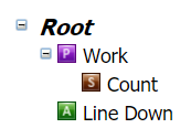
|The Root should look like the image below. | |||
{|style="margin:left;" | |||
|valign="top" | | |||
{|class="wikitable" style="background:white;" | |||
|- | |||
|[[File:CountPSM8.png|center|173px]] | |||
|} | |||
|} | |||
|} | |||
|} | |||
<br> | |||
---- | |||
<br> | |||
{|style="margin:left; width: 100px; background:#eaf3ff; padding:5px; border:2px solid #000000;" | |||
|- | |||
|<big>'''Step 14.'''</big> | |||
{|style="margin:left; width: 800px; background:#F0F0F0; padding:5px; border:2px solid #000000;" | |||
|valign="top" | | |||
|- | |||
|Select Save & Exit button. | |||
{|style="margin:left;" | |||
|valign="top" | | |||
{|class="wikitable" style="background:white;" | |||
|- | |||
|[[File:3139 11.png|center|250px]] | |||
|} | |||
|} | |||
|} | |||
|} | |||
<br> | |||
---- | |||
<br> | |||
{|style="margin:left; width: 100px; background:#eaf3ff; padding:5px; border:2px solid #000000;" | |||
|- | |||
|<big>'''Step 15.'''</big> | |||
{|style="margin:left; width: 800px; background:#F0F0F0; padding:5px; border:2px solid #000000;" | |||
|valign="top" | | |||
|- | |||
|Example of what the Screen will display. | |||
{|style="margin:left;" | |||
|valign="top" | | |||
{|class="wikitable" style="background:white; width: 775px;" | |||
|- | |||
|[[File:LinkCount1.png|center|700px]] | |||
|- | |||
|style="text-align:center" | '''Not Active''' - press the Start Work/Process button to enable a count. | |||
|} | |||
{|class="wikitable" style="background:white; width: 775px;" | |||
|- | |||
|[[File:LinkCount2.png|center|700px]] | |||
|- | |||
|style="text-align:center" | '''Active Count''' - press the Count button to add a count - press the End Work/Process button to disable the count. | |||
|} | |||
|} | |||
|} | |||
|} | |||
<br> | |||
---- | ---- | ||
---- | ---- | ||
<br> | |||
{|style="margin: auto; background:#eaf3ff; border:1px solid #2a4b8d" | {|style="margin: auto; background:#eaf3ff; border:1px solid #2a4b8d" | ||
|valign="top" | | |valign="top" | | ||
| Line 163: | Line 366: | ||
</inputbox> | </inputbox> | ||
|} | |} | ||
<br> | |||
[[Category:VT3000 Core Software]] | [[Category:VT3000 Core Software]] | ||
[[Category:Configuration]] | [[Category:Configuration]] | ||
[[Category:Count]] | [[Category:Count]] | ||
[[Category:PC Input Module]] | [[Category:PC Input Module]] | ||
Revision as of 15:58, 18 November 2021
|
|
Instructions
Step 1.
|
Step 2.
|
Step 3.
|
Step 4.
|
Step 5.
|
Step 6.
|
Step 7.
|
Step 8.
|
Step 9.
|
Step 10.
|
Step 11.
|
Step 12.
|
Step 13.
|
Step 14.
|
Step 15.
|
| ||||


