VT3000 Devices
Revision as of 13:23, 7 October 2022 by SupportAdmin (talk | contribs)

|

|

|

Overview
|

Device Abilities
| |||||||||||||||||||||||||||||||||||||||||||||||||||||||||||||||||||||||||||||||||||||||||||||||||||||||||||||||||||||||||
Basic Functionality
|


Device Properties
|

Monitoring Point
|
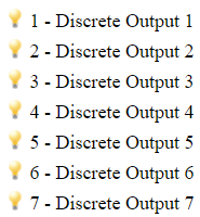
Discrete Outputs
|
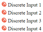
Discrete Inputs
|
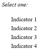
Indicators
|
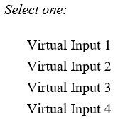
Virtual Inputs
|
Communications
|
Actions
|
|
|


|