Difference between revisions of "Home - Coordinator"
Jump to navigation
Jump to search

SupportAdmin (talk | contribs) |
SupportAdmin (talk | contribs) |
||
| (2 intermediate revisions by the same user not shown) | |||
| Line 9: | Line 9: | ||
|[[Image:EmailUsBtn.png|link=mailto:[email protected]?Subject=Help%20Needed%20Wiki&body=Type%20Message%20Here]] | |[[Image:EmailUsBtn.png|link=mailto:[email protected]?Subject=Help%20Needed%20Wiki&body=Type%20Message%20Here]] | ||
|} | |} | ||
<BR> | <BR> | ||
<div style="box-shadow: 0 0 10px 0 #b1d5ee inset; border-radius:5px; padding:10px; padding-left:20px; background:#ebf4fa;"> | |||
<div style="box-shadow: 0 | <span style="color:#00719e; font-family: Helvetica; font-size:150%; font-variant: small-caps; padding-left:20px;">'''General Information'''</span> | ||
<span style="color:#00719e; font-family: Helvetica; font-size: | :*The Coordinator is the device that receives information from the devices on the plant floor. | ||
:*The Coordinator communicates all information from the hardware devices to the VersaCall Software. | |||
:*This device communicates with hardware devices over a 900MHz band. VersaCall refers to this as our Mesh Network. | |||
:*Coordinators can be connected to the Computer/Server via USB port or over an Ethernet connection. | |||
</div> | </div> | ||
<BR> | <BR> | ||
<div style="box-shadow: 0 0 10px 0 #b1d5ee inset; border-radius:5px; padding:10px; padding-left:20px; background:#ebf4fa;"> | |||
<span style="color:#00719e; font-family: Helvetica; font-size:150%; font-variant: small-caps; padding-left:20px;">'''Specifications'''</span> | |||
<BR> | <BR> | ||
<span style="color:#90A4AE; font-size: | :<span style="color:#90A4AE; font-size:140%">'''<u>USB Connected</u>'''</span> | ||
:[[Image:USB-Coor-Dimensions-2.png|border|775px|link=Home - Coordinator]] | |||
<BR> | <BR> | ||
* | :<span style="color:#90A4AE; font-size:130%">'''Requirements'''</span> | ||
* | :*110v power outlet within 6 feet of placement/location. | ||
*Mounting location free of Metal Enclosures | :*Control Unit within 6 feet of placement/location. | ||
:*Mounting location free of Metal Enclosures. | |||
<BR> | <BR> | ||
<span style="color:#90A4AE; font-size:130%">'''Specifications'''</span> | :<span style="color:#90A4AE; font-size:130%">'''Specifications'''</span> | ||
:*Dimensions – 3.5” (W) x 4.5” (L) x 1.5” (H) | |||
:*(1) 6’ Power Cord (included) | |||
:*(1) 6’ USB Cord (included) | |||
:*(1) 7” Antenna (included) | |||
<BR> | <BR> | ||
:<span style="color:#90A4AE; font-size:140%">'''<u>Remote - RS-232 Connected</u>'''</span> | |||
:[[Image:Remote-Coor-Dimensions-2.png|border|775px|link=Home - Coordinator]] | |||
<BR> | <BR> | ||
:<span style="color:#90A4AE; font-size:130%">'''Requirements'''</span> | |||
:*(2) 110v power outlets within 6 feet of placement/location (Coordinator & RS-232). | |||
:*Coordinator & RS-232 within 6 feet of each other. | |||
:*Mounting location free of Metal Enclosures. | |||
:*Ethernet port near the placement/location of the RS-232. | |||
:*RS-232 will need to be assigned a Static IP Address or a DHCP Reserved address. | |||
<BR> | <BR> | ||
<span style="color:#90A4AE; font-size:130%">''' | :<span style="color:#90A4AE; font-size:130%">'''Specifications'''</span> | ||
:*Coordinator Dimensions – 3.5” (W) x 4.5” (L) x 1.5” (H) | |||
:*RS-232 Dimensions - s" (W) x 3.25" (L) x .75" (H) | |||
:*(2) 6’ Power Cords (included) | |||
:*(1) 6’ Serial Cable (included) | |||
:*(1) 7” Antenna (included) | |||
:*(1) Ethernet Cable (not included) | |||
<BR> | <BR> | ||
[[Image:RealPort- | :<span style="color:#90A4AE; font-size:140%">'''<u>Real-Port Connected</u>'''</span> | ||
:[[Image:RealPort-Dimensions2.png|border|775px|link=Home - Coordinator]] | |||
<BR> | <BR> | ||
<span style="color:#90A4AE; font-size:130%">'''Requirements'''</span> | :<span style="color:#90A4AE; font-size:130%">'''Requirements'''</span> | ||
:*110v power outlet within 6 feet of placement/location. | |||
:*Mounting location free of Metal Enclosures. | |||
:*Ethernet port near the placement/location of the RS-232. | |||
:*Pre-Installed Static IP Address (VersaCall) or DHCP Reserved IP Address based on the MAC Address of the Coordinator (Customer IT). | |||
<BR> | <BR> | ||
:<span style="color:#90A4AE; font-size:130%">'''Specifications'''</span> | |||
:*Dimensions – 3.5” (W) x 4.5” (L) x 1.5” (H) | |||
:*(1) 6’ Power Cord (included) | |||
:*(1) 6’ Ethernet Cord (included) | |||
:*(1) 7” Antenna (included) | |||
<span style="color:#90A4AE; font-size:130%">'''Specifications'''</span> | |||
*Dimensions – 3.5” (W) x 4.5” (L) x 1.5” (H) | |||
*(1) 6’ Power Cord (included) | |||
*(1) 6’ Ethernet Cord (included) | |||
*(1) 7” Antenna (included) | |||
</div> | </div> | ||
<BR> | <BR> | ||
<div style="box-shadow: 0 0 10px 0 #b1d5ee inset; border-radius:5px; padding:10px; padding-left:20px; background:#ebf4fa;"> | |||
<span style="color:#00719e; font-family: Helvetica; font-size:150%; font-variant: small-caps; padding-left:20px;">'''Install Guides'''</span> | |||
<BR> | <BR> | ||
::<span style="font-size:92%; line-height: 2.5em; border:thin solid #90A4AE; border-radius:5px; padding:5px">[[VT3000 - Install Coordinator - USB|'''Instructions on Installing a USB type Coordinator''']]</span> | ::<span style="font-size:92%; line-height: 2.5em; border:thin solid #90A4AE; border-radius:5px; padding:5px">[[VT3000 - Install Coordinator - USB|'''Instructions on Installing a USB type Coordinator''']]</span> | ||
::<span style="font-size:92%; line-height: 2.5em; border:thin solid #90A4AE; border-radius:5px; padding:5px">[[VT3000 - Install Coordinator - Remote - Same Subnet|'''Instructions on Installing an Ethernet/Remote Coordinator where the Coordinator & Computer/Server are on the Same Subnet''']]</span> | ::<span style="font-size:92%; line-height: 2.5em; border:thin solid #90A4AE; border-radius:5px; padding:5px">[[VT3000 - Install Coordinator - Remote - Same Subnet|'''Instructions on Installing an Ethernet/Remote Coordinator where the Coordinator & Computer/Server are on the Same Subnet''']]</span> | ||
| Line 95: | Line 79: | ||
</div> | </div> | ||
<BR> | <BR> | ||
<div style="box-shadow: 0 0 10px 0 #b1d5ee inset; border-radius:5px; padding:10px; padding-left:20px; background:#ebf4fa;"> | |||
<div style="box-shadow: 0 | <span style="color:#00719e; font-family: Helvetica; font-size:150%; font-variant: small-caps; padding-left:20px;">'''Step by Step Guides'''</span> | ||
<span style="color:#00719e; font-family: Helvetica; font-size: | |||
::<span style="font-size:92%; line-height: 2.5em; border:thin solid #90A4AE; border-radius:5px; padding:5px">[[VT3000 - Replace Coordinator - USB|'''Instructions on how to Replace a USB Coordinator''']]</span> | ::<span style="font-size:92%; line-height: 2.5em; border:thin solid #90A4AE; border-radius:5px; padding:5px">[[VT3000 - Replace Coordinator - USB|'''Instructions on how to Replace a USB Coordinator''']]</span> | ||
::<span style="font-size:92%; line-height: 2.5em; border:thin solid #90A4AE; border-radius:5px; padding:5px">[[VT3000 - Find Coordinator Settings|'''Instructions on how to get the Driver Settings for a Coordinator Setup on the System''']]</span> | ::<span style="font-size:92%; line-height: 2.5em; border:thin solid #90A4AE; border-radius:5px; padding:5px">[[VT3000 - Find Coordinator Settings|'''Instructions on how to get the Driver Settings for a Coordinator Setup on the System''']]</span> | ||
| Line 107: | Line 86: | ||
</div> | </div> | ||
<BR> | <BR> | ||
<div style="box-shadow: 0 0 10px 0 #b1d5ee inset; border-radius:5px; padding:10px; padding-left:20px; background:#ebf4fa;"> | |||
<div style="box-shadow: 0 | <span style="color:#00719e; font-family: Helvetica; font-size:150%; font-variant: small-caps; padding-left:10px;">'''Keyword Search'''</span> | ||
<span style="color:#00719e; font-family: Helvetica; font-size: | |||
{|style="margin:auto;" | {|style="margin:auto;" | ||
{|class="wikitable" style="align:center; width:600px;" | {|class="wikitable" style="align:center; width:600px;" | ||
| Line 122: | Line 98: | ||
</div> | </div> | ||
<br> | <br> | ||
[[File:VC Footer.png|center]] | [[File:VC Footer.png|center|link=Main Page]] | ||
{|style="background:transparent; color:black" border="0" height="200" align="center" valign="bottom" cellpadding=10px cellspacing=10px | {|style="background:transparent; color:black" border="0" height="200" align="center" valign="bottom" cellpadding=10px cellspacing=10px | ||
|+style="background:transparent| | |+style="background:transparent| | ||
Latest revision as of 20:09, 27 December 2023

|

|

|
General Information
- The Coordinator is the device that receives information from the devices on the plant floor.
- The Coordinator communicates all information from the hardware devices to the VersaCall Software.
- This device communicates with hardware devices over a 900MHz band. VersaCall refers to this as our Mesh Network.
- Coordinators can be connected to the Computer/Server via USB port or over an Ethernet connection.
Specifications
- USB Connected
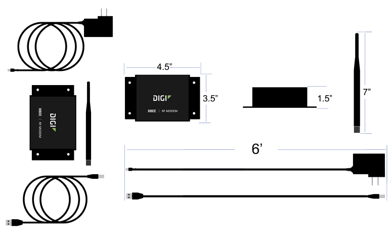
- Requirements
- 110v power outlet within 6 feet of placement/location.
- Control Unit within 6 feet of placement/location.
- Mounting location free of Metal Enclosures.
- Specifications
- Dimensions – 3.5” (W) x 4.5” (L) x 1.5” (H)
- (1) 6’ Power Cord (included)
- (1) 6’ USB Cord (included)
- (1) 7” Antenna (included)
- Remote - RS-232 Connected
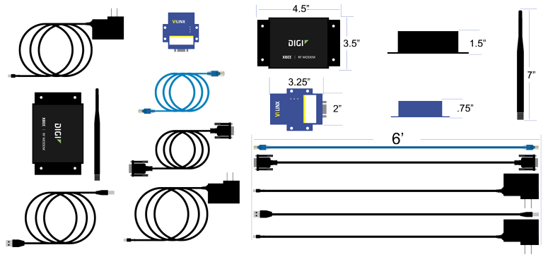
- Requirements
- (2) 110v power outlets within 6 feet of placement/location (Coordinator & RS-232).
- Coordinator & RS-232 within 6 feet of each other.
- Mounting location free of Metal Enclosures.
- Ethernet port near the placement/location of the RS-232.
- RS-232 will need to be assigned a Static IP Address or a DHCP Reserved address.
- Specifications
- Coordinator Dimensions – 3.5” (W) x 4.5” (L) x 1.5” (H)
- RS-232 Dimensions - s" (W) x 3.25" (L) x .75" (H)
- (2) 6’ Power Cords (included)
- (1) 6’ Serial Cable (included)
- (1) 7” Antenna (included)
- (1) Ethernet Cable (not included)
- Real-Port Connected
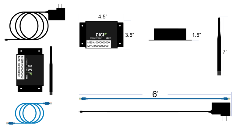
- Requirements
- 110v power outlet within 6 feet of placement/location.
- Mounting location free of Metal Enclosures.
- Ethernet port near the placement/location of the RS-232.
- Pre-Installed Static IP Address (VersaCall) or DHCP Reserved IP Address based on the MAC Address of the Coordinator (Customer IT).
- Specifications
- Dimensions – 3.5” (W) x 4.5” (L) x 1.5” (H)
- (1) 6’ Power Cord (included)
- (1) 6’ Ethernet Cord (included)
- (1) 7” Antenna (included)
Install Guides
- Instructions on Installing a USB type Coordinator
- Instructions on Installing an Ethernet/Remote Coordinator where the Coordinator & Computer/Server are on the Same Subnet
- Instructions on Installing an Ethernet/Remote Coordinator where the Coordinator & Computer/Server are on Different Subnets
- Instructions on Installing an Ethernet Connect Port X2 (Real-Port) Coordinator where the Coordinator & Computer/Server are on the Same Subnet
- Instructions on Installing an Ethernet Connect Port X2 (Real-Port) Coordinator where the Coordinator & Computer/Server are on Different Subnets
Step by Step Guides
Keyword Search
| Type Subject or Key Word to Query Archives |
|---|

|