Difference between revisions of "Home - Coordinator"
Jump to navigation
Jump to search

SupportAdmin (talk | contribs) |
SupportAdmin (talk | contribs) |
||
| Line 103: | Line 103: | ||
<div style="box-shadow:2px 2px 15px #90A4AE; border-radius:5px; padding:10px"> | <div style="box-shadow:2px 2px 15px #90A4AE; border-radius:5px; padding:10px"> | ||
{|style="margin:auto;" | {|style="margin:auto;" | ||
{|class="wikitable" | {|class="wikitable" style="align:center; width:600px;" | ||
|- | |- | ||
!<span style="color:#0054a6; font-size:120%"><big>Type Subject or Key Word to Query Archives</big></span> | !<span style="color:#0054a6; font-size:120%"><big>Type Subject or Key Word to Query Archives</big></span> | ||
Revision as of 14:28, 6 October 2023

|

|

|

- The Coordinator is the device that receives information from the devices on the plant floor.
- The Coordinator communicates all information from the hardware devices to the VersaCall Software.
- This device communicates with hardware devices over a 900MHz band. VersaCall refers to this as our Mesh Network.
- Coordinators can be connected to the Computer/Server via USB port or over an Ethernet connection.

USB Connected
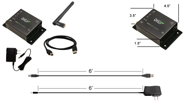
Requirements
- 110v power outlet within 6 feet of placement/location.
- Control Unit within 6 feet of placement/location.
- Mounting location free of Metal Enclosures.
Specifications
- Dimensions – 3.5” (W) x 4.5” (L) x 1.5” (H)
- (1) 6’ Power Cord (included)
- (1) 6’ USB Cord (included)
- (1) 7” Antenna (included)
Remote - RS-232 Connected

Requirements
- (2) 110v power outlets within 6 feet of placement/location (Coordinator & RS-232).
- Coordinator & RS-232 within 6 feet of each other.
- Mounting location free of Metal Enclosures.
- Ethernet port near the placement/location of the RS-232.
- RS-232 will need to be assigned a Static IP Address or a DHCP Reserved address.
Specifications
- Coordinator Dimensions – 3.5” (W) x 4.5” (L) x 1.5” (H)
- RS-232 Dimensions - s" (W) x 3.25" (L) x .75" (H)
- (2) 6’ Power Cords (included)
- (1) 6’ Serial Cable (included)
- (1) 7” Antenna (included)
- (1) Ethernet Cable (not included)
Real-Port Connected
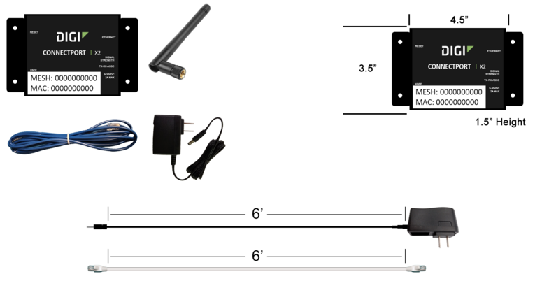
Requirements
- 110v power outlet within 6 feet of placement/location.
- Mounting location free of Metal Enclosures.
- Ethernet port near the placement/location of the RS-232.
- Pre-Installed Static IP Address (VersaCall) or DHCP Reserved IP Address based on the MAC Address of the Coordinator (Customer IT).
Specifications
- Dimensions – 3.5” (W) x 4.5” (L) x 1.5” (H)
- (1) 6’ Power Cord (included)
- (1) 6’ Ethernet Cord (included)
- (1) 7” Antenna (included)

- Instructions on Installing a USB type Coordinator
- Instructions on Installing an Ethernet/Remote Coordinator where the Coordinator & Computer/Server are on the Same Subnet
- Instructions on Installing an Ethernet/Remote Coordinator where the Coordinator & Computer/Server are on Different Subnets
- Instructions on Installing an Ethernet Connect Port X2 (Real-Port) Coordinator where the Coordinator & Computer/Server are on the Same Subnet
- Instructions on Installing an Ethernet Connect Port X2 (Real-Port) Coordinator where the Coordinator & Computer/Server are on Different Subnets

General Information

| Type Subject or Key Word to Query Archives |
|---|

|