VT3000 - Wired Input Connection (IO Module)

From Versacall Support
Jump to navigation Jump to search
Call Now 858-677-6766 SubmitTckBtn.png EmailUsBtn.png


GeneralHeader.png

Overview
The instructions in this guide apply to the I/O Module for the PSM, TIM, and Wireless Switch Contact Module. Two types of input circuits can be used in these modules, dry contact or DC signal. Each of the (4) contacts can be configured separately. The configuration is decided by the state of the associated switch (S1) and which of the 3 terminals the wiring is connected to. In either case, the yellow LEDs signify the state of the input. The red LEDs indicate that the module is powered.


Requirements
See Requirements Here
1. The VT3000 Core Software installed and running on your system.
2. A Coordinator must be setup, powered and communicating with the VT3000 Core Software.
3. Wiring from your machine must be run to the I/O Module.
4. An existing TIM, PSM or Switch Contact Module powered and communicating with the system.


Completion Steps
Completion Steps
CountParts.png
Count Steps
AlarmParts.png
Alarm Steps


DetailHeader.png

I/O Circuit Board
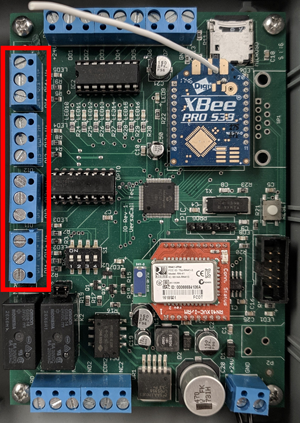
The Input Connectors can be found on the left side of the board.
CatInput2.png


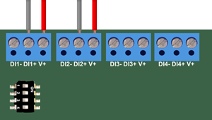
Dry Contact Connection
A Dry Contact means that the I/O Module circuit board will be providing power to the connection. No power is pulled from your equipment.
CatInput1.png


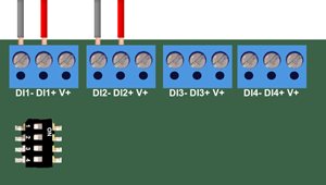
DC Signal Connection
A DC Signal Connection means that your equipment will be providing power to the I/O Module connection.
CatInput3.png


Dry Contact
The dry contact configuration looks for a contact closure/open between DI#+ and V+. There should be no voltage connected to this input. The associated switch should be in the ON position. If you need to switch between normally-open/normally-closed operations, this can be accomplished with in the VT3000 software by using the Inverted setting.


DC Signal
The DC signal configuration looks for a DC voltage input. This input is looking for a change in the voltage state from a high state of anything over 1.5 – 26 VDC to a low state of 0 - 0.9 VDC. The positive should be DI#+ and the negative end should be hooked up to DI#-. The associated switch should be in the OFF position. If the signal occurs on the rising (low to high) or falling (high to low) edge, this can setup in the VT3000 software by using the Inverted setting.


Downtime
Use this contact to signal when the equipment is in a down state (not producing). The user decides what constitutes downtime. Depending on the equipment, the signal can come from different sources.
PLC or Control Circuitry is the easiest method to pull a contact from. Many times this can come from a non-Auto Run state. It is possible to connect multiple relays in parallel to achieve the desired result.
Equipment can be considered down when there is a power loss.
Equipment can be considered down when the E-stop has been activated.
Equipment can be considered down when there is no power to a certain motor.


Count
Use this contact to signal when a part has been completed. Depending on the type of equipment, the contact can come from a variety of different sources.
A sensor such as an electronic eye can indicate a count when the plane is broken.
A signal such as a machine cycle can indicate when a count is completed.
An external button press from an operator can indicate when a count is completed


Equipment Fault
Use this contact to determine when equipment generates a fault.
This contact would come from a PLC or other control circuitry equipment where faults have been programmed into the equipment's logic.


Sensor Limit
Use this contact to determine when a sensor reaches a critical limit.
This requires a special type of sensor to trip a contact at a certain point.
Common examples are the monitoring of temperature, pressure or some fluid level


RelatedHowTos.png
Select a Guide Here
Setup Wired Input as an Alarm
Setup Wired Input as a Count


SearchHeader.png


VC Footer.png
Follow Us On LinkedIn View our Blog