Difference between revisions of "VT3000 - Add Wired Contact (Alarm)"
Jump to navigation
Jump to search
SupportAdmin (talk | contribs) |
SupportAdmin (talk | contribs) |
||
| (17 intermediate revisions by the same user not shown) | |||
| Line 1: | Line 1: | ||
= | {|style="background:transparent; color:black" border="0" height="230" align="center" valign="bottom" | ||
|+style="background:transparent| | |||
|-align="center" | |||
| | |||
|[[Image:CallUsBtn.png|Call Now 858-677-6766]] | |||
| | |||
[[ | |[[Image:SubmitTckBtn.png|link=https://www.versacall.com/customer-support/service-ticket]] | ||
| | |||
|[[Image:EmailUsBtn.png|link=mailto:[email protected]?Subject=Help%20Needed%20Wiki&body=Type%20Message%20Here]] | |||
|} | |||
<br> | |||
---- | |||
---- | |||
<br> | |||
[[File:GeneralHeader.png]] | |||
''' | <br> | ||
{|style="margin:left; width: 100px; background:#eaf3ff; padding:5px; border:2px solid #000000;" | |||
|- | |||
|<big>'''Overview'''</big> | |||
{|style="margin:left; width: 800px; background:#F0F0F0; padding:5px; border:2px solid #000000;" | |||
= | |valign="top" | | ||
|- | |||
|An I/O module is part of a PSM & TIM, the Switch Contact Module is an IO module without a touch screen interface. All of these can receive wired contacts from outside sources. After you have physically wired your contact into the IO module you will need to setup that Input. This guide explains how to setup the contact/input as an alarm/transition. | |||
|} | |||
|} | |||
<br> | |||
{|style="margin:left; width: 100px; background:#eaf3ff; padding:5px; border:2px solid #000000;" | |||
< | |- | ||
|<big>'''Requirements'''</big> | |||
{|style="margin:left; width: 800px; background:#F0F0F0; padding:5px; border:2px solid #000000;" | |||
''' | |valign="top" | | ||
{| class="wikitable mw-collapsible mw-collapsed" width="775px;" | |||
< | |- | ||
|style="text-align: center;" | '''See Requirements Here''' | |||
|- | |||
|'''1.''' The VT3000 Core Software installed and running on your system. | |||
|- | |||
|'''2.''' A Coordinator must be setup, powered and communicating with the VT3000 Core Software. | |||
|- | |||
|'''3.''' Switch Contact, TIM or PSM - the device must be powered and communicating with the system. | |||
''' | |- | ||
|'''4.''' Contact Wire from your machine must be wired into one of the Inputs on the I/O (Part 1). | |||
|} | |||
|} | |||
|} | |||
<br> | |||
{|style="margin:left; width: 100px; background:#eaf3ff; padding:5px; border:2px solid #000000;" | |||
''' | |- | ||
|<big>'''Completion Steps'''</big> | |||
{|style="margin:left; width: 800px; background:#F0F0F0; padding:5px; border:2px solid #000000;" | |||
|valign="top" | | |||
|- | |||
|[[File:AlarmParts.png|center|652px]] | |||
|} | |||
''' | |} | ||
<br> | |||
---- | |||
---- | |||
<br> | |||
[[File:VideoHeader.png]] | |||
<br> | |||
''' | {|style="margin:left; width: 100px; background:#eaf3ff; padding:5px; border:2px solid #000000;" | ||
|- | |||
|<big>'''Video'''</big> | |||
{|style="margin:left; width: 800px; background:#F0F0F0; padding:5px; border:2px solid #000000;" | |||
< | |valign="top" | | ||
|- | |||
|align=center|<embedvideo service="youtube">https://www.youtube.com/watch?v=YP3LCvmx8uw</embedvideo> | |||
|} | |||
|} | |||
<br> | |||
---- | |||
---- | |||
<br> | |||
[[File:InstructionHeader.png]] | |||
<br> | |||
{|style="margin:left; width: 100px; background:#eaf3ff; padding:5px; border:2px solid #000000;" | |||
|- | |||
|<big>'''Step 1.'''</big> | |||
</ | {|style="margin:left; width: 800px; background:#F0F0F0; padding:5px; border:2px solid #000000;" | ||
|valign="top" | | |||
|- | |||
|Open the VT3000 web interface – select VT3000 Core Software - log in – select Configuration – select Devices. | |||
{|style="margin:left;" | |||
< | |valign="top" | | ||
{|class="wikitable" style=" align="center; " background:white;" | |||
</ | |- | ||
|[[File:3110_1.png|center|93px]] || [[File:3139 2.png|center|93px]] | |||
|- | |||
|style="text-align:center" | '''Configuration''' ||style="text-align:center" | '''Devices''' | |||
|} | |||
|} | |||
|} | |||
|} | |||
<br> | |||
---- | |||
<br> | |||
{|style="margin:left; width: 100px; background:#eaf3ff; padding:5px; border:2px solid #000000;" | |||
|- | |||
File: | |<big>'''Step 2.'''</big> | ||
{|style="margin:left; width: 800px; background:#F0F0F0; padding:5px; border:2px solid #000000;" | |||
|valign="top" | | |||
|- | |||
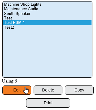
|Select the Device that you wired the contact into in Part # 1 - this would be the wires pulled from your machine into the VersaCall I/O or Switch Contact Module. | |||
{|style="margin:left;" | |||
|valign="top" | | |||
{|class="wikitable" style=" align="center; " background:white;" | |||
< | |- | ||
< | |[[File:3139 4.png|center|320px]] | ||
|} | |||
|} | |||
|} | |||
|} | |||
<br> | |||
---- | |||
< | <br> | ||
{|style="margin:left; width: 100px; background:#eaf3ff; padding:5px; border:2px solid #000000;" | |||
</ | |- | ||
|<big>'''Step 3.'''</big> | |||
{|style="margin:left; width: 800px; background:#F0F0F0; padding:5px; border:2px solid #000000;" | |||
|valign="top" | | |||
|- | |||
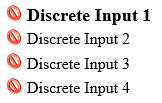
|Select the Discrete Inputs tab. | |||
{|style="margin:left;" | |||
|valign="top" | | |||
{|class="wikitable" style="background:white;" | |||
|- | |||
|[[File:3139 5.png|center|619px]] | |||
|} | |||
|} | |||
File: | |} | ||
|} | |||
<br> | |||
---- | |||
<br> | |||
{|style="margin:left; width: 100px; background:#eaf3ff; padding:5px; border:2px solid #000000;" | |||
< | |- | ||
|<big>'''Step 4.'''</big> | |||
</ | {|style="margin:left; width: 800px; background:#F0F0F0; padding:5px; border:2px solid #000000;" | ||
|valign="top" | | |||
|- | |||
|Select the input (VersaCall I/O or Switch Contact Module) that you wired your machine connection into. | |||
{|style="margin:left;" | |||
|valign="top" | | |||
{|class="wikitable" style="background:white;" | |||
|- | |||
|[[File:3139 7.png|center|162px]] | |||
|} | |||
|} | |||
|} | |||
|} | |||
File: | <br> | ||
---- | |||
<br> | |||
{|style="margin:left; width: 100px; background:#eaf3ff; padding:5px; border:2px solid #000000;" | |||
|- | |||
|<big>'''Step 5.'''</big> | |||
< | {|style="margin:left; width: 800px; background:#F0F0F0; padding:5px; border:2px solid #000000;" | ||
|valign="top" | | |||
< | |- | ||
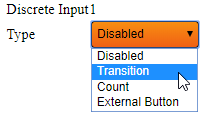
|The Input Properties window will show - by default, the type will be set to Disabled - select the down arrow - select Transition. | |||
{|style="margin:left;" | |||
|valign="top" | | |||
{|class="wikitable" style="background:white;" | |||
|- | |||
|[[File:WireAlarm1.png|center|202px]] | |||
< | |} | ||
|} | |||
|} | |||
'' | |} | ||
<br> | |||
---- | |||
<br> | |||
= | {|style="margin:left; width: 100px; background:#eaf3ff; padding:5px; border:2px solid #000000;" | ||
|- | |||
|<big>'''Step 6.'''</big> | |||
{|style="margin:left; width: 800px; background:#F0F0F0; padding:5px; border:2px solid #000000;" | |||
|valign="top" | | |||
|- | |||
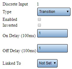
|Discrete Input Properties: | |||
{|style="margin:left;" | |||
|valign="top" | | |||
{|class="wikitable" style="background:white; width:775px;" | |||
|- | |||
|[[File:WireAlarm2.png|center|234px]] | |||
|} | |||
{|class="wikitable" style="background:white; width: 775px;" | |||
|- | |||
|'''Type''' – select Transition for an Alarm - contact will either be On or Off. | |||
< | |- | ||
|'''Enabled''' – select to enable input - this will make the input active at all times. For most configurations this would be check marked. The exception would be if you want to only enable the input when a Process is started/running. | |||
|- | |||
|'''Inverted''' – select if wired signal is inverted (contact always on - off trips the alarm). | |||
|- | |||
|'''On Delay''' – leave as default - causes a delay in milliseconds before the contact is turned on. | |||
|- | |||
|'''Off Delay''' – leave as default - causes a delay in milliseconds before the contact is turned off. | |||
|- | |||
|'''Linked To''' – leave this field as Not Set - this item will be addressed in Part # 3. | |||
|} | |||
|} | |||
|} | |||
|} | |||
<br> | |||
-------- | |||
<br> | |||
{|style="margin:left; width: 100px; background:#eaf3ff; padding:5px; border:2px solid #000000;" | |||
|- | |||
|<big>'''Step 7.'''</big> | |||
{|style="margin:left; width: 800px; background:#F0F0F0; padding:5px; border:2px solid #000000;" | |||
|valign="top" | | |||
|- | |||
|After the Transition is setup click on the Save & Exit button. The setup must be saved first before it can be linked in the following steps (Part #3). | |||
{|style="margin:left;" | |||
|valign="top" | | |||
{|class="wikitable" style="background:white;" | |||
|- | |||
|[[File:3104 14.png|center|240px]] | |||
|} | |||
|} | |||
|} | |||
|} | |||
<br> | |||
---- | |||
---- | |||
<br> | |||
{|style="margin:auto;" | |||
|+ | |||
[[File:RelatedHowTos.png|center]] | |||
|align="center" | | |||
{| class="wikitable mw-collapsible mw-collapsed" width="400px;" | |||
|- | |||
|style="text-align: center;" | '''Select a Guide Here''' | |||
|- | |||
|[[VT3000 - Wired Input Connection (IO Module)|How to Wire an Input]] | |||
|- | |||
|[[VT3000 - Add Contact Alarm - Dual State|Setup an Input as a Dual State Alarm]] | |||
|- | |||
|[[VT3000 - Add Contact Alarm - Tri-State|Setup an Input as a Tri-State Alarm]] | |||
|- | |||
|[[VT3000 - Add Contact Alarm - Tri-State w/Reason on Acknowledge|Setup an Input as a Tri-State w/Reason on Acknowledge Alarm]] | |||
|- | |||
|[[VT3000 - Enable Disable an Input using a Process|Turn an Input On/Off with a Process]] | |||
|} | |||
|} | |||
<br> | |||
---- | |||
<br> | |||
{|style="margin:auto;" | |||
|+ | |||
[[File:SearchHeader.png|center]] | |||
|align="center" | | |||
{|class="wikitable" | |||
|- | |||
|<inputbox>type=search</inputbox> | |||
|} | |||
|} | |||
<br> | |||
---- | |||
<br> | |||
[[File:VC Footer.png|center]] | |||
{|style="background:transparent; color:black" border="0" height="200" align="center" valign="bottom" cellpadding=10px cellspacing=10px | |||
|+style="background:transparent| | |||
|-align="center" | |||
| | |||
|[[File:LinkedIn.png|Follow Us On LinkedIn|link=https://www.linkedin.com/company/versacall/]] | |||
| | |||
|[[File:BlogIcon.png|View our Blog|link=https://www.versacall.com/blog/]] | |||
|} | |||
<br> | |||
[[Category:VT3000 Core Software]] | [[Category:VT3000 Core Software]] | ||
[[Category:Configuration]] | [[Category:Configuration]] | ||
| Line 198: | Line 275: | ||
[[Category:TIM]] | [[Category:TIM]] | ||
[[Category:PSM]] | [[Category:PSM]] | ||
[[Category:Switch Contact Module]] | |||
Latest revision as of 15:36, 2 January 2024

|

|

|
Overview
|
Requirements
|
| Completion Steps
|
| Video
|
Step 1.
|
Step 2.
|
Step 3.
|
Step 4.
|
Step 5.
|
Step 6.
|
Step 7.
|
|
|

|


