VT3000 - Add Contact Alarm - Tri-State w/Reason on Acknowledge

From Versacall Support
Jump to navigation Jump to search
Call Now 858-677-6766 SubmitTckBtn.png EmailUsBtn.png


GeneralHeader.png

Overview
Once you have a contact wired to an input on the IO as a Transition (Alarm), you will need to set up the Monitoring Point in the device configuration. This guide explains how to setup a Tri-State w/Reason on Acknowledge Contact Alarm. When the Contact is On the Alarm will be set/active on the Touch Screen. The Operator will be able to select a Specify button on the Touch Screen to respond to the Alarm and select a Reason from a list. When the Contact is Off the Alarm will be cleared/removed from the Touch Screen. If the Operator does not select to Acknowledge/Specify a Reason on the alarm before the contact turns Off, there will be no way for the Operator to acknowledge/specify the alarm.


Requirements
See Requirements Here
1. The VT3000 Core Software installed and running on your system.
2. A Coordinator must be setup, powered and communicating with the VT3000 Core Software.
3. Switch Contact, TIM or PSM - the device must be powered and communicating with the system.
4. Contact Wire from your machine must be wired into one of the Inputs on the I/O (Part 1).
5. The Input for the contact must be setup in the configuration for the device (Part 2).


Completion Steps
AlarmParts.png


VideoHeader.png

Video


InstructionHeader.png

Step 1.
Open the VT3000 web interface – select VT3000 Core Software - log in – select Configuration – select Devices.
3110 1.png
3139 2.png
Configuration Devices


Step 2.
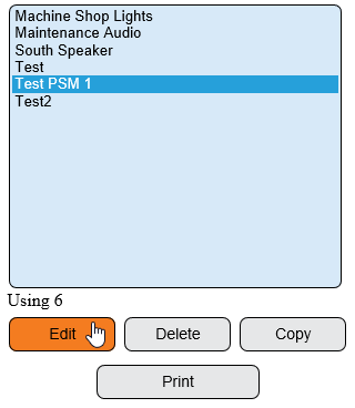
Select the Device that you wired your contact from the machine into the IO (Part 1) and setup the input on (Part 2) - select Edit.
3139 4.png


Step 3.
Select the Monitoring Points tab.
Reason1.png


Step 4.
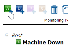
Contact alarms must be Root Alarms, they cannot be a subordinate of a Process. Select Root - select the add Alarm icon.
WireAlarm4.png
WireAlarm5.png


Step 5.
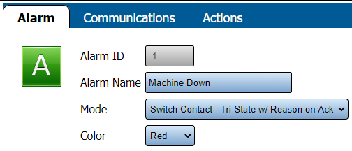
Alarm Properties - select the options shown below:
InputAlarm2.png
Alarm Name – enter a name for the Alarm.
Mode – select Switch Contact - Tri-State w/Reason on Ack.
Color – select Red.


Step 6.
Select the Add Alarm icon from the Monitoring Points toolbox with your new switch contact alarm selected.
InputAlarm3.png


Step 7.
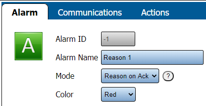
Alarm Properties - select the options shown below:
InputAlarm4.png
Alarm Name – enter a name for the Reason.
Mode – select Reason on Ack.
Color – select Red.


Step 8.
Repeat step 6 & 7 to setup multiple Reasons.


Step 9.
Select Save & Exit button.
3139 11.png


Step 10.
Select the Device that you added the Alarm to in the steps above - select Edit.
3139 4.png


Step 11.
Select Discrete Inputs tab.
3139 5.png


Step 12.
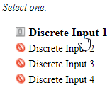
Select the Discrete Input that you wired your machine into (Part 1) and setup as a Transition (Part 2).
WireAlarm7.png


Step 13.
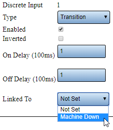
Transition Properties - select the down arrow on the Linked To field - select the Switch Contact - Tri-State w/Reason on Ack alarm that you added in Step 5 (our example shows Machine Down).
WireAlarm8.png


Step 14.
Select Save & Exit button.
3139 11.png


Step 15.
Select Save & Exit button.
You will need to update the TIM/PSM, CLICK HERE for instructions.


RelatedHowTos.png
Select a Guide Here
Add an Alarm with a Reasons (Root Cause)
Add an Alarm as a Label
Add an Alarm to a PSM
Add Communications to an Alarm
How to Wire an Input
Setup a Wired Contact (Input) as a Dual State Alarm
Setup a Wired Contact (Input) as a Tri-State Alarm]]
How to Turn an Input On/Off with a Process


SearchHeader.png


VC Footer.png
Follow Us On LinkedIn View our Blog