VT3000 - Add Communications (Alarm)

From Versacall Support
Jump to navigation Jump to search
Call Now 858-677-6766 SubmitTckBtn.png EmailUsBtn.png


GeneralHeader.png

Overview
When an Alarm is added to a module, there is an option to setup communications to outputs. The user will define what the message with say and what Route is to be used. Depending on the type of alarm that you have setup (Dual State, Tri-State or Reason on Ack/Clear), you will be able to setup a communication for each State of the Alarm.


Requirements
See Requirements Here
1. The VT3000 Core Software installed and running on your system.
2. A Coordinator must be setup, powered and communicating with the VT3000 Core Software.
3. Software PC Call Station, PC BSC or PC Input Module - the plug in must be loaded in the VT3000 Core software and there must be at least one license remaining.
4. Hardware Call Station, BSC, TIM or PSM - the device must be powered and communicating with the system.
5. Routes & Outputs must be setup prior to starting this quide.
6. Know what Routes are to used with each Alarm and what the message needs to be.


VideoHeader.png

Video


InstructionHeader.png

Step 1.
Open the VT3000 web interface – select VT3000 Core Software - log in – select Configuration – select Devices.
3110 1.png
3139 2.png
Configuration Devices


Step 2.
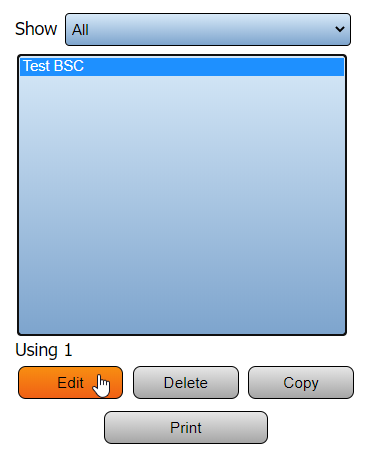
Select the Device that you want to setup communications on - select Edit.
BSCCount3.png


Step 3.
Select the Monitoring Points tab.
Reason1.png


Step 4.
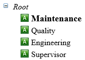
Select the Alarm that you want to setup communications for from the Root.
3140 6.png


Step 5.
Select the Communications tab from the Alarm Properties cell.
Reason2.png


Step 6.
Icons in the Communications tool box:
3140 8.png
3140 9.png
3140 10.png
3140 11.png
3140 12.png
Add a Path Delete a Path Duplicate a Path Copy a Path Paste a Path


Step 7.
Select the Add a Path icon.
3140 13.png


Step 8.
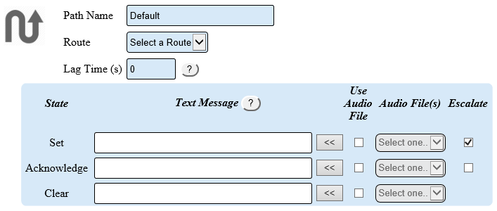
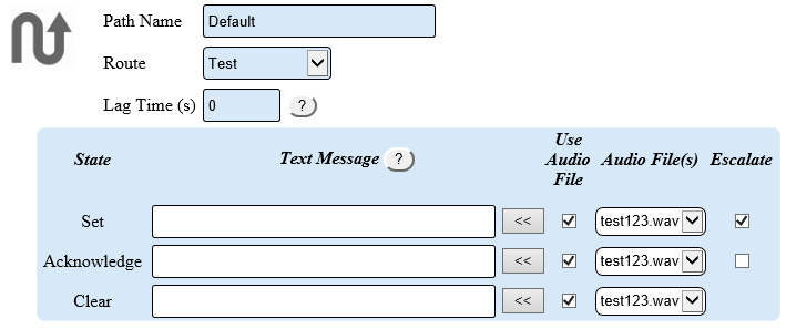
Path Properties:
3140 14.png
Path Name – leave this as Default or enter a name.
Route – use the down arrow to select a route from a list.
Lag Time – enter a number of seconds to elapse before the first communication is sent.
State – Dual State Alarm will show Set & Clear. Tri-State Alarm will show Set, Acknowledge and Clear.
Text Message – enter the message used for email, texts & pagers.
Audio File – select the audio file if you have uploaded MP3 or WAV files to the system. By default the system will use text to speech over radio & voice phone calls.
Escalate – selected if the outputs in the route should be escalated to the next level.


Step 9.
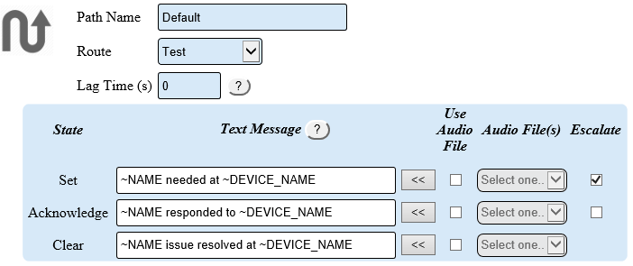
Example of a communication path setup for Email, Text messages, Text To Speech Phone & Radio calls.
3140 15.png
NOTE: Use the grey arrow buttons next to the text box to insert a default message. This translates to the following, “Maintenance needed at Test”.


Step 10.
Example of a communications path used for playing MP3 or WAV files over Radios & Telephone Calls.
3140 16.png
NOTE: Select the specific audio file for the alarm, state and device. All audio files must be recored & uploaded to the VT3000 system.


Step 11.
Select the Add a Path icon.
3140 17.png


RelatedHowTos.png
Select a Guide Here
Add an Alarm with a Reasons (Root Cause)
Add an Alarm as a Label
Add an Alarm to a PSM
Adding a Route
Setup a Wired Contact (Input) as a Dual State Alarm
Setup a Wired Contact (Input) as a Tri-State Alarm
Setup a Wired Contact (Input) as a Tri-State w/Reason on Acknowledge Alarm
Install a Device Plug In (PC Module, BSC or PSM)


SearchHeader.png


VC Footer.png
Follow Us On LinkedIn View our Blog