Difference between revisions of "VT3000 - Add Wired Contact (Alarm)"
SupportAdmin (talk | contribs) |
SupportAdmin (talk | contribs) |
||
| Line 5: | Line 5: | ||
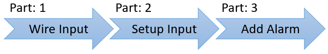
=Completion Cycle= | =Completion Cycle= | ||
[[File:AlarmParts.png]] | [[File:AlarmParts.png]] | ||
=Requirements= | =Requirements= | ||
'''1.''' VT3000 Core installed and running on the system. | '''1.''' VT3000 Core installed and running on the system. | ||
'''2.''' The Contact wire from your machine must be wired into one of the Inputs on the I/O Module (Part 1). If you have not completed this step, [[VT3000 - Wired Input Connection (IO Module)|'''CLICK HERE''']] for instructions. | |||
'''3.''' The TIM, PSM or Switch Contact Module must be powered and communicating with the VersaCall software. | |||
Revision as of 21:31, 2 September 2021
Overview
An I/O module is part of a PSM & TIM, the Switch Contact Module is an IO module without a touch screen interface. All of these can receive wired contacts from outside sources. After you have physically wired your contact into the IO module you will need to setup that Input. This guide explains how to setup the contact/input as an alarm/transition.
Completion Cycle

Requirements
    1.  VT3000 Core installed and running on the system.
    2.  The Contact wire from your machine must be wired into one of the Inputs on the I/O Module (Part 1).  If you have not completed this step, CLICK HERE for instructions.
    3.  The TIM, PSM or Switch Contact Module must be powered and communicating with the VersaCall software.
Instructions
1. Open the VT3000 software – login – select Configuration – select Devices.

Configuration

Devices


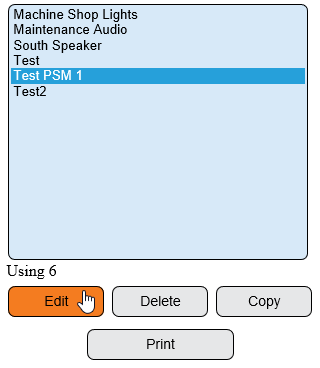
2. Select an existing device to edit or select to add a new device.
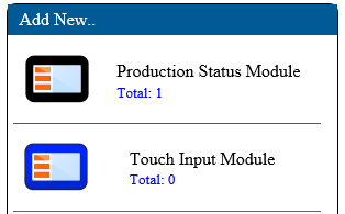
New

Existing

3. Select the Discrete Inputs tab.

4. Select the wired input.

5. The Input Properties window will show - type will be set to Disabled - select the down arrow - select Transition.

6. The following options will be available after Transition is selected.

    a. Type – select Transition
    b. Enabled – select to enable input.
    c. Inverted – select if wired signal is inverted (contact always on - off trips the alarm).
    d. On Delay – leave as default.
    e. Off Delay – leave as default.
    f. Linked To – used to link an alarm with the contact. Alarms set up as Switch Contacts will appear in the list.
7. Example:
8. After the Transition is setup click on the Save & Exit button. The setup must be saved first before it can be linked in the following steps.

| ||||