Difference between revisions of "VT3000 - Replacement - Touch Screen"
Jump to navigation
Jump to search
SupportAdmin (talk | contribs) |
SupportAdmin (talk | contribs) m (Text replacement - "https://www.linkedin.com/company/versacall-technologies-inc-/mycompany/" to "https://www.linkedin.com/company/versacall/") |
||
| (5 intermediate revisions by the same user not shown) | |||
| Line 1: | Line 1: | ||
=Overview= | {|style="background:transparent; color:black" border="0" height="230" align="center" valign="bottom" | ||
When a Touch Screen is broken or stops operating properly, a new touch will be needed. Once the Touch Screen is received it will need to be paired with the I/O module through the Bluetooth connection. All touch screens connect to the I/O module in the same manner (BSC, TIM or PSM). | |+style="background:transparent| | ||
|-align="center" | |||
| | |||
=Requirements= | |[[Image:CallUsBtn.png|Call Now 858-677-6766]] | ||
| | |||
'''1.''' | |[[Image:SubmitTckBtn.png|link=https://www.versacall.com/customer-support/service-ticket]] | ||
| | |||
''' | |[[Image:EmailUsBtn.png|link=mailto:[email protected]?Subject=Help%20Needed%20Wiki&body=Type%20Message%20Here]] | ||
|} | |||
''' | <br> | ||
---- | |||
---- | |||
= | <br> | ||
[[File:GeneralHeader.png]] | |||
'''1.''' | <br> | ||
{|style="margin:left; width: 100px; background:#eaf3ff; padding:5px; border:2px solid #000000;" | |||
|- | |||
File:bscin18.png | |<big>'''Overview'''</big> | ||
< | {|style="margin:left; width: 800px; background:#F0F0F0; padding:5px; border:2px solid #000000;" | ||
|valign="top" | | |||
|- | |||
'''2.''' | |When a Touch Screen is broken or stops operating properly, a new touch will be needed. Once the Touch Screen is received it will need to be paired with the I/O module through the Bluetooth connection. All touch screens connect to the I/O module in the same manner (BSC, TIM or PSM). | ||
|} | |||
|} | |||
File: | <br> | ||
< | {|style="margin:left; width: 100px; background:#eaf3ff; padding:5px; border:2px solid #000000;" | ||
|- | |||
|<big>'''Requirements'''</big> | |||
{|style="margin:left; width: 800px; background:#F0F0F0; padding:5px; border:2px solid #000000;" | |||
< | |valign="top" | | ||
{| class="wikitable mw-collapsible mw-collapsed" width="775px;" | |||
|- | |||
'''3.''' | |style="text-align: center;" | '''See Requirements Here''' | ||
|- | |||
|'''1.''' The VT3000 Core Software installed and running on your system. | |||
File:bscin19.png | |- | ||
< | |'''2.''' A Coordinator must be setup, powered and communicating with the VT3000 Core Software. | ||
|- | |||
< | |'''3.''' A BSC, TIM or PSM I/O Module Powered and communicating with the VT3000 Software. | ||
|- | |||
< | |'''4.''' A Touch Screen powered and showing the VersaCall HMI interface. | ||
|} | |||
|} | |||
|} | |||
'''4.''' | <br> | ||
---- | |||
---- | |||
File:Connect1.png | <br> | ||
< | [[File:InstructionHeader.png]] | ||
<br> | |||
{|style="margin:left; width: 100px; background:#eaf3ff; padding:5px; border:2px solid #000000;" | |||
|- | |||
'''5.''' | |<big>'''Step 1.'''</big> | ||
{|style="margin:left; width: 800px; background:#F0F0F0; padding:5px; border:2px solid #000000;" | |||
|valign="top" | | |||
File:Connect2.png | |- | ||
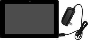
< | |Unpack the New Touch Screen and remove it from the box. | ||
{|style="margin:left;" | |||
|valign="top" | | |||
'''6.''' | {|class="wikitable" style="background:white; align:center;" | ||
|- | |||
|[[File:bscin18.png|center|300px]] | |||
File:Connect3.png | |} | ||
|} | |||
|} | |||
|} | |||
<br> | |||
---- | |||
< | {|style="margin:left; width: 100px; background:#eaf3ff; padding:5px; border:2px solid #000000;" | ||
|- | |||
< | |<big>'''Step 2.'''</big> | ||
{|style="margin:left; width: 800px; background:#F0F0F0; padding:5px; border:2px solid #000000;" | |||
|valign="top" | | |||
''' | |- | ||
|Unplug power from the old touch screen and remove it from the mount. Find the IO Module and make a note of the Bluetooth address printed on the sticker next to the power cord. | |||
< | {|style="margin:left;" | ||
|valign="top" | | |||
{|class="wikitable" style="background:white; align:center;" | |||
|- | |||
|[[File:PSMBlue.png|center|350px]] | |||
|} | |||
|} | |||
|} | |||
File: | |} | ||
<br> | |||
---- | |||
{|style="margin:left; width: 100px; background:#eaf3ff; padding:5px; border:2px solid #000000;" | |||
|- | |||
|<big>'''Step 3.'''</big> | |||
< | {|style="margin:left; width: 800px; background:#F0F0F0; padding:5px; border:2px solid #000000;" | ||
|valign="top" | | |||
< | |- | ||
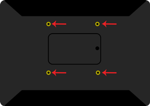
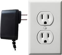
|Mount the New Touch Screen in the same place that you removed the old touch screen. Once it is mounted plug in the power cord to an outlet. | |||
{|style="margin:left;" | |||
''' | |valign="top" | | ||
{|class="wikitable" style="background:white; align:center;" | |||
< | |- | ||
|[[File:bscin19.png|center|300px]] || [[File:bscin25.png|center|200px]] | |||
|} | |||
|} | |||
|} | |||
|} | |||
<br> | |||
---- | |||
<br> | |||
{|style="margin:left; width: 100px; background:#eaf3ff; padding:5px; border:2px solid #000000;" | |||
|- | |||
|<big>'''Step 4.'''</big> | |||
{|style="margin:left; width: 800px; background:#F0F0F0; padding:5px; border:2px solid #000000;" | |||
|valign="top" | | |||
|- | |||
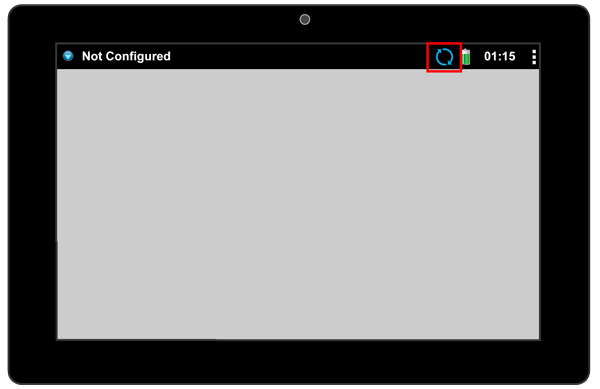
File: | |You will see a message appear stating the screen needs to connected to an IO. The Bluetooth icon will show arrows indicating it is trying to connect. | ||
{|style="margin:left;" | |||
|valign="top" | | |||
{|class="wikitable" style="background:white; align:center;" | |||
|- | |||
|[[File:Connect1.png|center|600px]] | |||
< | |} | ||
|} | |||
< | |} | ||
|} | |||
<br> | |||
---- | |||
<br> | |||
{|style="margin:left; width: 100px; background:#eaf3ff; padding:5px; border:2px solid #000000;" | |||
|- | |||
< | |<big>'''Step 5.'''</big> | ||
{|style="margin:left; width: 800px; background:#F0F0F0; padding:5px; border:2px solid #000000;" | |||
|valign="top" | | |||
''' | |- | ||
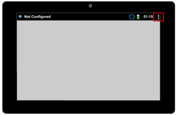
|Select the 3 squares in the top right corner of the screen. | |||
< | {|style="margin:left;" | ||
|valign="top" | | |||
{|class="wikitable" style="background:white; align:center;" | |||
|- | |||
|[[File:Connect2.png|center|600px]] | |||
|} | |||
|} | |||
|} | |||
File: | |} | ||
<br> | |||
---- | |||
<br> | |||
{|style="margin:left; width: 100px; background:#eaf3ff; padding:5px; border:2px solid #000000;" | |||
|- | |||
< | |<big>'''Step 6.'''</big> | ||
{|style="margin:left; width: 800px; background:#F0F0F0; padding:5px; border:2px solid #000000;" | |||
< | |valign="top" | | ||
|- | |||
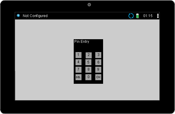
|Enter the PIN - by default this is 7047 - select OK. | |||
{|style="margin:left;" | |||
|valign="top" | | |||
{|class="wikitable" style="background:white; align:center;" | |||
|- | |||
|[[File:Connect3.png|center|600px]] | |||
< | |} | ||
|} | |||
|} | |||
''' | |} | ||
<br> | |||
< | ---- | ||
<br> | |||
{|style="margin:left; width: 100px; background:#eaf3ff; padding:5px; border:2px solid #000000;" | |||
|- | |||
|<big>'''Step 7.'''</big> | |||
{|style="margin:left; width: 800px; background:#F0F0F0; padding:5px; border:2px solid #000000;" | |||
|valign="top" | | |||
|- | |||
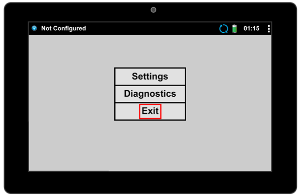
|Select Exit on the menu that appears. | |||
{|style="margin:left;" | |||
|valign="top" | | |||
{|class="wikitable" style="background:white; align:center;" | |||
|- | |||
|[[File:Connect4.png|center|600px]] | |||
|} | |||
|} | |||
|} | |||
|} | |||
<br> | |||
---- | |||
<br> | |||
{|style="margin:left; width: 100px; background:#eaf3ff; padding:5px; border:2px solid #000000;" | |||
File: | |- | ||
|<big>'''Step 8.'''</big> | |||
{|style="margin:left; width: 800px; background:#F0F0F0; padding:5px; border:2px solid #000000;" | |||
|valign="top" | | |||
|- | |||
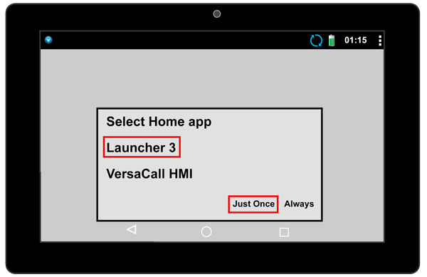
|Select Launcher 3 from the menu that appears - select Just Once. | |||
{|style="margin:left;" | |||
|valign="top" | | |||
< | {|class="wikitable" style="background:white; align:center;" | ||
|- | |||
|[[File:Connect5.png|center|600px]] | |||
|} | |||
|} | |||
|} | |||
|} | |||
<br> | |||
---- | |||
<br> | |||
{|style="margin:left; width: 100px; background:#eaf3ff; padding:5px; border:2px solid #000000;" | |||
|- | |||
|<big>'''Step 9.'''</big> | |||
{|style="margin:left; width: 800px; background:#F0F0F0; padding:5px; border:2px solid #000000;" | |||
|valign="top" | | |||
|- | |||
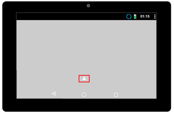
|You will be sent to the Android home screen. Select the Up facing arrow in the middle of the screen. | |||
{|style="margin:left;" | |||
|valign="top" | | |||
{|class="wikitable" style="background:white; align:center;" | |||
|- | |||
|[[File:Connect6.png|center|600px]] | |||
|} | |||
|} | |||
|} | |||
|} | |||
<br> | |||
---- | |||
<br> | |||
{|style="margin:left; width: 100px; background:#eaf3ff; padding:5px; border:2px solid #000000;" | |||
|- | |||
|<big>'''Step 10.'''</big> | |||
{|style="margin:left; width: 800px; background:#F0F0F0; padding:5px; border:2px solid #000000;" | |||
|valign="top" | | |||
|- | |||
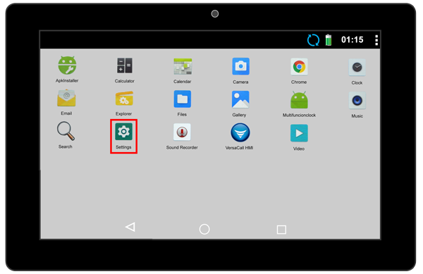
|The Apps screen will load - select the Settings App Icon. | |||
{|style="margin:left;" | |||
|valign="top" | | |||
{|class="wikitable" style="background:white; align:center;" | |||
|- | |||
|[[File:Connect7.png|center|600px]] | |||
|} | |||
|} | |||
|} | |||
|} | |||
<br> | |||
---- | ---- | ||
{|style="margin: | <br> | ||
{|style="margin:left; width: 100px; background:#eaf3ff; padding:5px; border:2px solid #000000;" | |||
|- | |||
|<big>'''Step 11.'''</big> | |||
{|style="margin:left; width: 800px; background:#F0F0F0; padding:5px; border:2px solid #000000;" | |||
|valign="top" | | |||
|- | |||
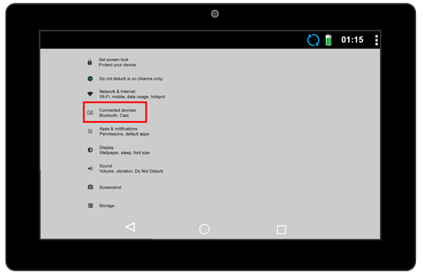
|Select the Connected Devices (Bluetooth, Cast) option. | |||
{|style="margin:left;" | |||
|valign="top" | | |||
{|class="wikitable" style="background:white; align:center;" | |||
|- | |||
|[[File:Connect8.png|center|600px]] | |||
|} | |||
|} | |||
|} | |||
|} | |||
<br> | |||
---- | |||
<br> | |||
{|style="margin:left; width: 100px; background:#eaf3ff; padding:5px; border:2px solid #000000;" | |||
|- | |||
|<big>'''Step 12.'''</big> | |||
{|style="margin:left; width: 800px; background:#F0F0F0; padding:5px; border:2px solid #000000;" | |||
|valign="top" | | |||
|- | |||
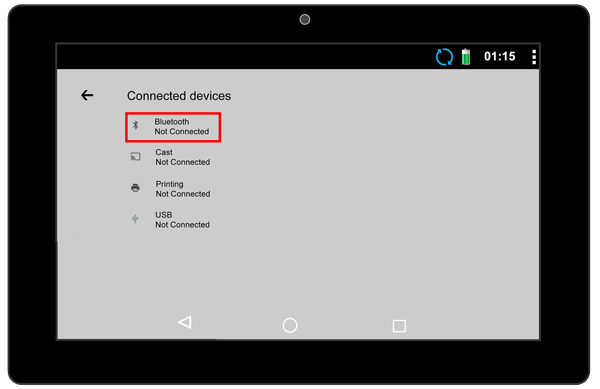
|Select Bluetooth (turn Bluetooth on with the toggle switch if it is off) from the Connected Devices menu. | |||
{|style="margin:left;" | |||
|valign="top" | | |||
{|class="wikitable" style="background:white; align:center;" | |||
|- | |||
|[[File:Connect9.png|center|600px]] | |||
|} | |||
|} | |||
|} | |||
|} | |||
<br> | |||
---- | |||
<br> | |||
{|style="margin:left; width: 100px; background:#eaf3ff; padding:5px; border:2px solid #000000;" | |||
|- | |||
|<big>'''Step 13.'''</big> | |||
{|style="margin:left; width: 800px; background:#F0F0F0; padding:5px; border:2px solid #000000;" | |||
|valign="top" | | |||
|- | |||
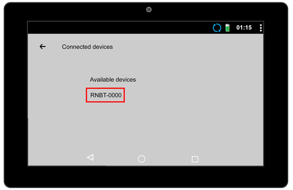
|A list of Bluetooth addresses will populate. Using the Bluetooth address that you wrote down in Step 2, use the last 4 numbers and find "RNBT-(those 4 numbers)" on the list - select it. | |||
{|style="margin:left;" | |||
|valign="top" | | |||
{|class="wikitable" style="background:white; align:center;" | |||
|- | |||
|[[File:Connect10.png|center|600px]] | |||
|} | |||
|} | |||
|} | |||
|} | |||
<br> | |||
---- | |||
<br> | |||
{|style="margin:left; width: 100px; background:#eaf3ff; padding:5px; border:2px solid #000000;" | |||
|- | |||
|<big>'''Step 14.'''</big> | |||
{|style="margin:left; width: 800px; background:#F0F0F0; padding:5px; border:2px solid #000000;" | |||
|valign="top" | | |||
|- | |||
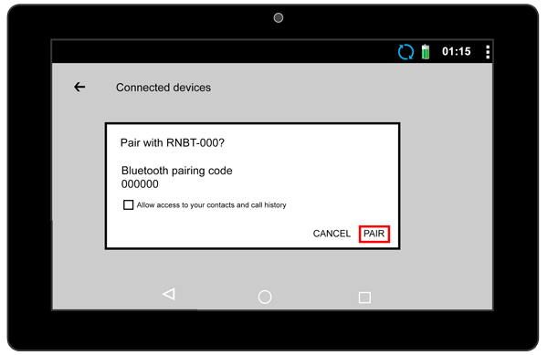
|After a few seconds a Pairing window will show - select the Pair option. | |||
{|style="margin:left;" | |||
|valign="top" | | |||
{|class="wikitable" style="background:white; align:center;" | |||
|- | |||
|[[File:Connect11.png|center|600px]] | |||
|} | |||
|} | |||
|} | |||
|} | |||
<br> | |||
---- | |||
<br> | |||
{|style="margin:left; width: 100px; background:#eaf3ff; padding:5px; border:2px solid #000000;" | |||
|- | |||
|<big>'''Step 15.'''</big> | |||
{|style="margin:left; width: 800px; background:#F0F0F0; padding:5px; border:2px solid #000000;" | |||
|valign="top" | | |||
|- | |||
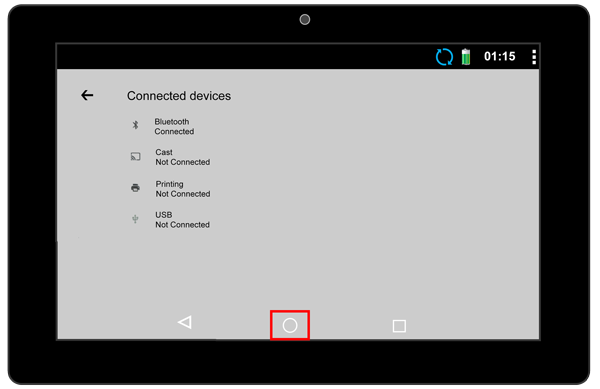
|After a few seconds the Connected Devices screen will show again. You may get a notification that states the pair was successful. Select the Circle (Home Icon) at the bottom of the screen. | |||
{|style="margin:left;" | |||
|valign="top" | | |||
{|class="wikitable" style="background:white; align:center;" | |||
|- | |||
|[[File:Connect12.png|center|600px]] | |||
|} | |||
|} | |||
|} | |||
|} | |||
<br> | |||
---- | |||
<br> | |||
{|style="margin:left; width: 100px; background:#eaf3ff; padding:5px; border:2px solid #000000;" | |||
|- | |||
|<big>'''Step 16.'''</big> | |||
{|style="margin:left; width: 800px; background:#F0F0F0; padding:5px; border:2px solid #000000;" | |||
|valign="top" | | |||
|- | |||
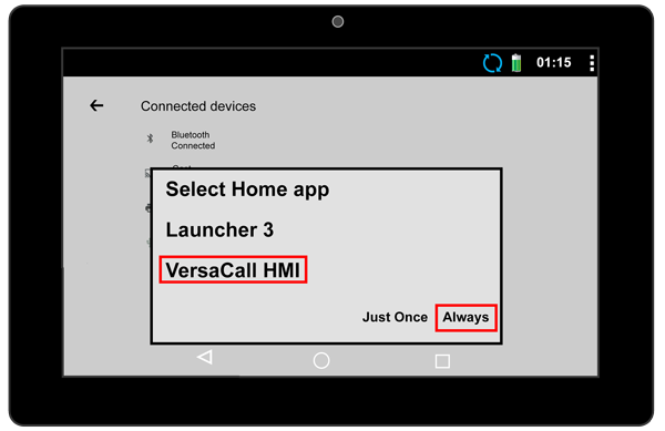
|Select VersaCall HMI from the pop up menu - select Always. | |||
{|style="margin:left;" | |||
|valign="top" | | |||
{|class="wikitable" style="background:white; align:center;" | |||
|- | |||
|[[File:Connect13.png|center|600px]] | |||
|} | |||
|} | |||
|} | |||
|} | |||
<br> | |||
---- | |||
<br> | |||
{|style="margin:left; width: 100px; background:#eaf3ff; padding:5px; border:2px solid #000000;" | |||
|- | |||
|<big>'''Step 17.'''</big> | |||
{|style="margin:left; width: 800px; background:#F0F0F0; padding:5px; border:2px solid #000000;" | |||
|valign="top" | | |||
|- | |||
|You will be returned to the VersaCall screen. Select the 3 squares in the top right corner. | |||
{|style="margin:left;" | |||
|valign="top" | | |||
{|class="wikitable" style="background:white; align:center;" | |||
|- | |||
|[[File:Connect2.png|center|600px]] | |||
|} | |||
|} | |||
|} | |||
|} | |||
<br> | |||
---- | |||
<br> | |||
{|style="margin:left; width: 100px; background:#eaf3ff; padding:5px; border:2px solid #000000;" | |||
|- | |||
|<big>'''Step 18.'''</big> | |||
{|style="margin:left; width: 800px; background:#F0F0F0; padding:5px; border:2px solid #000000;" | |||
|valign="top" | | |||
|- | |||
|Enter the same PIN as you did in Step 3 - select the OK button. | |||
{|style="margin:left;" | |||
|valign="top" | | |||
{|class="wikitable" style="background:white; align:center;" | |||
|- | |||
|[[File:Connect3.png|center|600px]] | |||
|} | |||
|} | |||
|} | |||
|} | |||
<br> | |||
---- | |||
<br> | |||
{|style="margin:left; width: 100px; background:#eaf3ff; padding:5px; border:2px solid #000000;" | |||
|- | |||
|<big>'''Step 19.'''</big> | |||
{|style="margin:left; width: 800px; background:#F0F0F0; padding:5px; border:2px solid #000000;" | |||
|valign="top" | | |||
|- | |||
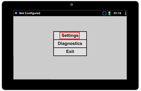
|Select Settings from the menu. | |||
{|style="margin:left;" | |||
|valign="top" | | |||
{|class="wikitable" style="background:white; align:center;" | |||
|- | |||
|[[File:Connect15.png|center|600px]] | |||
|} | |||
|} | |||
|} | |||
|} | |||
<br> | |||
---- | |||
<br> | |||
{|style="margin:left; width: 100px; background:#eaf3ff; padding:5px; border:2px solid #000000;" | |||
|- | |||
|<big>'''Step 20.'''</big> | |||
{|style="margin:left; width: 800px; background:#F0F0F0; padding:5px; border:2px solid #000000;" | |||
|valign="top" | | |||
|- | |||
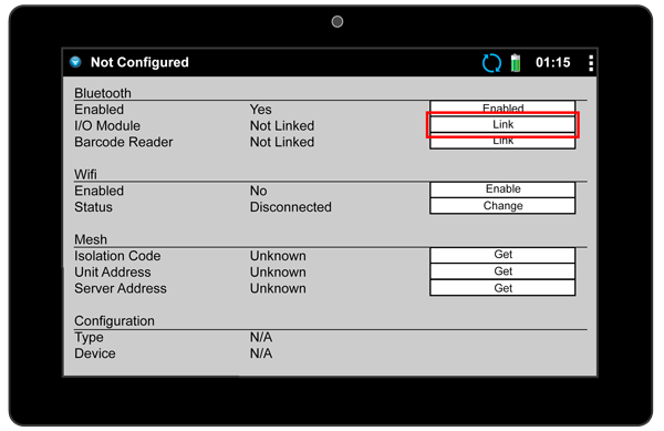
|Select the Link button in-line with the IO Module Heading under Bluetooth. | |||
{|style="margin:left;" | |||
|valign="top" | | |||
{|class="wikitable" style="background:white; align:center;" | |||
|- | |||
|[[File:Connect16.png|center|600px]] | |||
|} | |||
|} | |||
|} | |||
|} | |||
<br> | |||
---- | |||
<br> | |||
{|style="margin:left; width: 100px; background:#eaf3ff; padding:5px; border:2px solid #000000;" | |||
|- | |||
|<big>'''Step 21.'''</big> | |||
{|style="margin:left; width: 800px; background:#F0F0F0; padding:5px; border:2px solid #000000;" | |||
|valign="top" | | |||
|- | |||
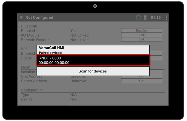
|On the pop up window you will see the Bluetooth address of the pairing that was made in the previous steps - select it. | |||
{|style="margin:left;" | |||
|valign="top" | | |||
{|class="wikitable" style="background:white; align:center;" | |||
|- | |||
|[[File:Connect17.png|center|600px]] | |||
|} | |||
|} | |||
|} | |||
|} | |||
<br> | |||
---- | |||
<br> | |||
{|style="margin:left; width: 100px; background:#eaf3ff; padding:5px; border:2px solid #000000;" | |||
|- | |||
|<big>'''Step 22.'''</big> | |||
{|style="margin:left; width: 800px; background:#F0F0F0; padding:5px; border:2px solid #000000;" | |||
|valign="top" | | |||
|- | |||
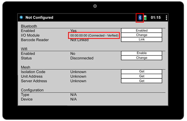
|After a few seconds the page will refresh and show the IO Module as connecting. Wait until the status shows " Connected - Verified". | |||
{|style="margin:left;" | |||
|valign="top" | | |valign="top" | | ||
{| class=" | {|class="wikitable" style="background:white; align:center;" | ||
|- | |- | ||
|[[ | |[[File:Connect18.png|center|600px]] | ||
|} | |||
|} | |||
|} | |||
|} | |||
<br> | |||
---- | |||
<br> | |||
{|style="margin:left; width: 100px; background:#eaf3ff; padding:5px; border:2px solid #000000;" | |||
|- | |||
|<big>'''Step 23.'''</big> | |||
{|style="margin:left; width: 800px; background:#F0F0F0; padding:5px; border:2px solid #000000;" | |||
|valign="top" | | |||
|- | |- | ||
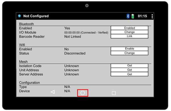
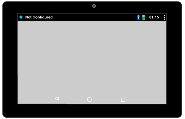
| | |Once the status shows Verified select the Home icon (Circle at the bottom of the screen). | ||
{|style="margin:left;" | |||
|valign="top" | | |||
{|class="wikitable" style="background:white; align:center;" | |||
|- | |- | ||
|[[ | |[[File:Connect19.png|center|600px]] | ||
|} | |||
|} | |||
|} | |||
|} | |} | ||
<br> | |||
---- | |||
<br> | |||
{|style="margin:left; width: 100px; background:#eaf3ff; padding:5px; border:2px solid #000000;" | |||
|- | |||
|<big>'''Step 24.'''</big> | |||
{|style="margin:left; width: 800px; background:#F0F0F0; padding:5px; border:2px solid #000000;" | |||
|valign="top" | | |||
|- | |||
|The IO and Touch Screen are now connected, you will need to update the configuration. Use one of the links below to get instructions on sending/updating the configuration. | |||
{|style="margin:left;" | |||
|valign="top" | | |valign="top" | | ||
{| class=" | {|class="wikitable" style="background:white; align:center; width:775px;" | ||
|- | |||
|[[File:Connect20.png|center|600px]] | |||
|} | |||
{|class="wikitable" style="background:white; align:center; width:775px;" | |||
|- | |||
|[[VT3000 - Send a New Configuration to a BSC|'''Click Here''']] for instructions on sending a Configuration to a New/Not Configured BSC. | |||
|- | |- | ||
|''' | |[[VT3000 - Send a New Configuration to a TIM or PSM|'''Click Here''']] for instructions on sending a Configuration to a New/Not Configured TIM, PSM. | ||
|- | |- | ||
|''' | |[[VT3000 - Update Configuration - TIM, PSM, BSC|'''Click Here''']] for instructions on Updating the configuration on an existing BSC, TIM, or PSM. | ||
|} | |} | ||
|} | |} | ||
|} | |||
|} | |||
<br> | |||
---- | |||
---- | |||
<br> | |||
{|style="margin:auto;" | |||
|+ | |||
[[File:RelatedHowTos.png|center]] | |||
|align="center" | | |||
{| class="wikitable mw-collapsible mw-collapsed" width="400px;" | |||
|- | |||
|style="text-align: center;" | '''Select a Guide Here''' | |||
|- | |||
|[[VT3000 - Pairing an Existing Touch Screen|Guide on Pairing an IO with an Existing Touch Screen - BSC TIM PSM]] | |||
|- | |||
|[[VT3000 - Test - Bluetooth Signal Strength|Test the Signal Strength of the Bluetooth Connection on a BSC, TIM or PSM]] | |||
|- | |||
|[[VT3000 - Update Date/Time on Tablet|Set the Correct Day & Time on a Touch Screen - BSC TIM PSM]] | |||
|} | |||
|} | |||
<br> | |||
---- | ---- | ||
<br> | |||
{|style="margin:auto;" | {|style="margin:auto;" | ||
|+ | |||
[[File:SearchHeader.png|center]] | |||
|align="center" | | |align="center" | | ||
{|class="wikitable" | {|class="wikitable" | ||
|- | |- | ||
|<inputbox>type=search</inputbox> | |<inputbox>type=search</inputbox> | ||
|} | |} | ||
|} | |||
<br> | |||
---- | ---- | ||
<br> | |||
[[File:VC Footer.png|center]] | |||
{|style="background:transparent; color:black" border="0" height="200" align="center" valign="bottom" cellpadding=10px cellspacing=10px | |||
|+style="background:transparent| | |||
|-align="center" | |||
| | |||
|[[File:LinkedIn.png|Follow Us On LinkedIn|link=https://www.linkedin.com/company/versacall/]] | |||
| | |||
|[[File:BlogIcon.png|View our Blog|link=https://www.versacall.com/blog/]] | |||
|} | |||
<br> | |||
[[Category:VT3000 Core Software]] | [[Category:VT3000 Core Software]] | ||
[[Category:Device Hardware]] | [[Category:Device Hardware]] | ||
Latest revision as of 19:28, 20 April 2023

|

|

|
Overview
|
Requirements
|
Step 1.
|
Step 2.
|
Step 3.
|
Step 4.
|
Step 5.
|
Step 6.
|
Step 7.
|
Step 8.
|
Step 9.
|
Step 10.
|
Step 11.
|
Step 12.
|
Step 13.
|
Step 14.
|
Step 15.
|
Step 16.
|
Step 17.
|
Step 18.
|
Step 19.
|
Step 20.
|
Step 21.
|
Step 22.
|
Step 23.
|
Step 24.
|
|
|

|


