Difference between revisions of "VT3000 - Find Coordinator Settings"
Jump to navigation
Jump to search
SupportAdmin (talk | contribs) |
SupportAdmin (talk | contribs) |
||
| Line 1: | Line 1: | ||
=Overview | {|style="margin:left;" | ||
If you have a need to check the Coordinator settings or if a VersaCall Technician asks you provide the settings, the instructions below will show you have to find them. | |valign="top" | | ||
{|class="wikitable" style="background:#eaf3ff;" | |||
|- | |||
=Requirements | !style="text-align: left;"|<big>'''Overview'''</big> | ||
|- | |||
'''1.''' VT3000 Core Software installed and running on your system. | |If you have a need to check the Coordinator settings or if a VersaCall Technician asks you provide the settings, the instructions below will show you have to find them. | ||
|} | |||
'''2.''' A | |} | ||
{|style="margin:left;" | |||
|valign="top" | | |||
{|class="wikitable mw-collapsible mw-collapsed" style="background:#eaf3ff; width: 800px;" | |||
!style="text-align: left;"|<big>'''Requirements'''</big> | |||
|- | |||
|'''1.''' The VT3000 Core Software installed and running on your system. | |||
|- | |||
|'''2.''' A Coordinator must be setup, powered and communicating with the VT3000 Core Software. | |||
|} | |||
|} | |||
Revision as of 15:55, 7 September 2021
|
|
Instructions
1. Open VT3000 web interface – log in – select Administration – select System Settings – select Service.
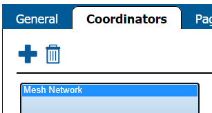
2. Select the Coordinators tab on the Service Settings page.
3. Select your Coordinator from the list so that it is highlighted.
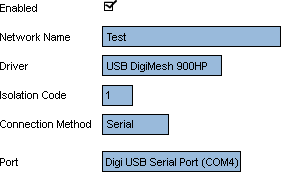
4. On the right side of the list you will see these settings for a USB Coordinator:
    a. Enabled – will be check marked to enable the device.
    b. Network Name – Coordinator Name.
    c. Driver – USB Digi Mesh 900HP.
    d. Isolation Code – this is set to 1 unless VersaCall instructs you to change it.
    e. Port – will show as USB Serial Port (COM#). The COM number will differ from the screen shot in most cases.
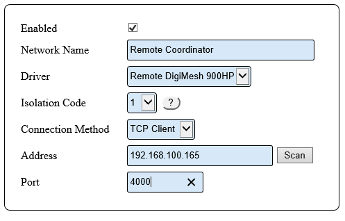
5. On the right side of the list you will see these settings for a Remote Coordinator:
    a. Enabled – will be check marked to enable the device.
    b. Network Name – Coordinator Name.
    c. Driver – will be Remote DigiMesh 900HP.
    d. Isolation Code – leave this set to 1 unless VersaCall instructs you to change it.
    e. Connection Method -  will be TCP Client.
    f. Address -  will have the Static IP address of the RS-232 device.
    e. Port – will be set to 4000.
6. Ensure that you select Discard & Exit so that nothing is changed.


