Difference between revisions of "VT3000 - Change Device ISO Code - VT3000 Software - BSC, TIM, PSM"
Jump to navigation
Jump to search
SupportAdmin (talk | contribs) |
SupportAdmin (talk | contribs) |
||
| (10 intermediate revisions by the same user not shown) | |||
| Line 1: | Line 1: | ||
=Overview= | {|style="background:transparent; color:black" border="0" height="230" align="center" valign="bottom" | ||
An Isolation Code is the specific channel used with a coordinator. Different Isolation Codes are required for facilities with multiple coordinators. New devices are shipped with a default Isolation Code of 1. This method will work for BSC, TIM or PSM I/O Module, Switch Contact Module or Wireless Controls Module. If you have a Call Station, please use one of the ISO Code methods found on the Categories - Call Station page. | |+style="background:transparent| | ||
|-align="center" | |||
| | |||
=Requirements= | |[[Image:CallUsBtn.png|Call Now 858-677-6766]] | ||
| | |||
'''1.''' The VT3000 Core Software installed and running on your system. | |[[Image:SubmitTckBtn.png|link=https://www.versacall.com/customer-support/service-ticket]] | ||
| | |||
'''2.''' At least | |[[Image:EmailUsBtn.png|link=mailto:[email protected]?Subject=Help%20Needed%20Wiki&body=Type%20Message%20Here]] | ||
|} | |||
'''3.''' At least one Switch Contact, Wireless Controls Module, BSC, TIM or PSM | <br> | ||
---- | |||
---- | |||
<br> | |||
[[File:GeneralHeader.png]] | |||
<br> | |||
{|style="margin:left; width: 100px; background:#eaf3ff; padding:5px; border:2px solid #000000;" | |||
|- | |||
|<big>'''Overview'''</big> | |||
< | {|style="margin:left; width: 800px; background:#F0F0F0; padding:5px; border:2px solid #000000;" | ||
File: | |valign="top" | | ||
< | |- | ||
|An Isolation Code is the specific channel used with a coordinator. Different Isolation Codes are required for facilities with multiple coordinators. New devices are shipped with a default Isolation Code of 1. This method will work for BSC, TIM or PSM I/O Module, Switch Contact Module or Wireless Controls Module. If you have a Call Station, please use one of the ISO Code methods found on the Categories - Call Station page. | |||
|} | |||
''' | |} | ||
<br> | |||
< | {|style="margin:left; width: 100px; background:#eaf3ff; padding:5px; border:2px solid #000000;" | ||
|- | |||
|<big>'''Requirements'''</big> | |||
< | {|style="margin:left; width: 800px; background:#F0F0F0; padding:5px; border:2px solid #000000;" | ||
|valign="top" | | |||
{| class="wikitable mw-collapsible mw-collapsed" width="775px;" | |||
|- | |||
|style="text-align: center;" | '''See Requirements Here''' | |||
< | |- | ||
File: | |'''1.''' The VT3000 Core Software installed and running on your system. | ||
< | |- | ||
|'''2.''' At least one Coordinator setup, powered and communicating with the VT3000 Core Software. | |||
|- | |||
''' | |'''3.''' At least one Switch Contact, Wireless Controls Module, BSC, TIM or PSM powered & communicating with the system. | ||
|} | |||
|} | |||
File: | |} | ||
< | <br> | ||
---- | |||
---- | |||
''' | <br> | ||
[[File:VideoHeader.png]] | |||
<br> | |||
File: | {|style="margin:left; width: 100px; background:#eaf3ff; padding:5px; border:2px solid #000000;" | ||
|- | |||
|<big>'''Video'''</big> | |||
{|style="margin:left; width: 800px; background:#F0F0F0; padding:5px; border:2px solid #000000;" | |||
''' | |valign="top" | | ||
|- | |||
< | |align=center|<embedvideo service="youtube">https://www.youtube.com/watch?v=osHI4uMT1no</embedvideo> | ||
|} | |||
< | |} | ||
<br> | |||
---- | |||
''' | ---- | ||
<br> | |||
[[File:InstructionHeader.png]] | |||
File: | <br> | ||
{|style="margin:left; width: 100px; background:#eaf3ff; padding:5px; border:2px solid #000000;" | |||
|- | |||
|<big>'''Step 1.'''</big> | |||
{|style="margin:left; width: 800px; background:#F0F0F0; padding:5px; border:2px solid #000000;" | |||
|valign="top" | | |||
|- | |||
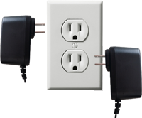
|Ensure the Touch Screen & IO Module are plugged in and powered. | |||
{|style="margin:left;" | |||
|valign="top" | | |||
{|class="wikitable" style=" align="center; " background:white;" | |||
|- | |||
|[[File:Bscin4.png|center|200px]] | |||
|} | |||
|} | |||
|} | |||
|} | |||
<br> | |||
---- | |||
<br> | |||
{|style="margin:left; width: 100px; background:#eaf3ff; padding:5px; border:2px solid #000000;" | |||
|- | |||
|<big>'''Step 2.'''</big> | |||
{|style="margin:left; width: 800px; background:#F0F0F0; padding:5px; border:2px solid #000000;" | |||
|valign="top" | | |||
|- | |||
|Open the VT3000 web interface – select VT3000 Core Software - log in – select Diagnostics – select Device Status. | |||
{|style="margin:left;" | |||
|valign="top" | | |||
{|class="wikitable" style=" align="center; " background:white;" | |||
|- | |||
|[[File:3215 2.png|center|101px]] || [[File:3215 3.png|center|101px]] | |||
|- | |||
|style="text-align:center" | '''Diagnostics''' ||style="text-align:center" | '''Device Status''' | |||
|} | |||
|} | |||
|} | |||
|} | |||
<br> | |||
---- | |||
<br> | |||
{|style="margin:left; width: 100px; background:#eaf3ff; padding:5px; border:2px solid #000000;" | |||
|- | |||
|<big>'''Step 3.'''</big> | |||
{|style="margin:left; width: 800px; background:#F0F0F0; padding:5px; border:2px solid #000000;" | |||
|valign="top" | | |||
|- | |||
|The device MUST show on Device Status - use the Mesh Address to identify it - select the Options link on the right side of the page/row. | |||
{|style="margin:left;" | |||
|valign="top" | | |||
{|class="wikitable" style="background:white;" | |||
|- | |||
|[[File:3215 4.png|center|740px]] | |||
|} | |||
|} | |||
|} | |||
|} | |||
<br> | |||
---- | ---- | ||
<br> | |||
{|style="margin:left; width: 100px; background:#eaf3ff; padding:5px; border:2px solid #000000;" | |||
|- | |||
|<big>'''Step 4.'''</big> | |||
{|style="margin:left; width: 800px; background:#F0F0F0; padding:5px; border:2px solid #000000;" | |||
|valign="top" | | |||
|- | |||
|Select Commands. | |||
{|style="margin:left;" | |||
|valign="top" | | |||
{|class="wikitable" style=" align="center; " background:white;" | |||
|- | |||
|[[File:3215 5.png|center|491px]] | |||
|} | |||
|} | |||
|} | |||
|} | |||
<br> | |||
---- | |||
<br> | |||
{|style="margin:left; width: 100px; background:#eaf3ff; padding:5px; border:2px solid #000000;" | |||
|- | |||
|<big>'''Step 5.'''</big> | |||
{|style="margin:left; width: 800px; background:#F0F0F0; padding:5px; border:2px solid #000000;" | |||
|valign="top" | | |||
|- | |||
|Select the down arrow in Command field. | |||
{|style="margin:left;" | |||
|valign="top" | | |||
{|class="wikitable" style="background:white;" | |||
|- | |||
|[[File:3215 6.png|center|335px]] | |||
|} | |||
|} | |||
|} | |||
|} | |||
<br> | |||
---- | |||
<br> | |||
{|style="margin:left; width: 100px; background:#eaf3ff; padding:5px; border:2px solid #000000;" | |||
|- | |||
|<big>'''Step 6.'''</big> | |||
{|style="margin:left; width: 800px; background:#F0F0F0; padding:5px; border:2px solid #000000;" | |||
|valign="top" | | |||
|- | |||
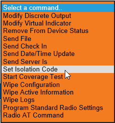
|Select Set Isolation Code from the menu. | |||
{|style="margin:left;" | |||
|valign="top" | | |||
{|class="wikitable" style=" align="center; " background:white;" | |||
|- | |||
|[[File:3215 7.png|center|229px]] | |||
|} | |||
|} | |||
|} | |||
|} | |||
<br> | |||
---- | |||
<br> | |||
{|style="margin:left; width: 100px; background:#eaf3ff; padding:5px; border:2px solid #000000;" | |||
|- | |||
|<big>'''Step 7.'''</big> | |||
{|style="margin:left; width: 800px; background:#F0F0F0; padding:5px; border:2px solid #000000;" | |||
|valign="top" | | |||
|- | |||
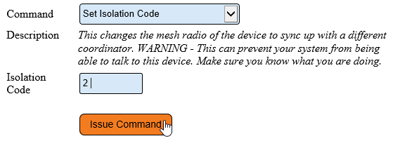
|Enter the Isolation Code you want to switch to – select the Issue Command button. | |||
{|style="margin:left;" | |||
|valign="top" | | |||
{|class="wikitable" style=" align="center; " background:white;" | |||
|- | |||
|[[File:3215 8.png|center|559px]] | |||
|} | |||
|} | |||
|} | |||
|} | |||
<br> | |||
---- | |||
<br> | |||
{|style="margin:left; width: 100px; background:#eaf3ff; padding:5px; border:2px solid #000000;" | |||
|- | |||
|<big>'''Step 8.'''</big> | |||
{|style="margin:left; width: 800px; background:#F0F0F0; padding:5px; border:2px solid #000000;" | |||
|valign="top" | | |||
|- | |||
|Select Diagnostics – select Device Status. | |||
{|style="margin:left;" | |||
|valign="top" | | |||
{|class="wikitable" style=" align="center; " background:white;" | |||
|- | |||
|[[File:3215 2.png|center|101px]] || [[File:3215 3.png|center|101px]] | |||
|- | |||
|style="text-align:center" | '''Diagnostics''' ||style="text-align:center" | '''Device Status''' | |||
|} | |||
|} | |||
|} | |||
|} | |||
<br> | |||
---- | |||
<br> | |||
{|style="margin:left; width: 100px; background:#eaf3ff; padding:5px; border:2px solid #000000;" | |||
|- | |||
|<big>'''Step 9.'''</big> | |||
{|style="margin:left; width: 800px; background:#F0F0F0; padding:5px; border:2px solid #000000;" | |||
|valign="top" | | |||
|- | |||
|Find the device that you switched the ISO Code on - under the Network Name, ensure it is showing the correct name of the Coordinator. | |||
{|style="margin:left;" | |||
|valign="top" | | |||
{|class="wikitable" style=" align="center; " background:white;" | |||
|- | |||
|[[File:StatusDevice.png|center|700px]] | |||
|} | |||
|} | |||
|} | |||
|} | |||
<br> | |||
---- | |||
---- | |||
<br> | |||
{|style="margin:auto;" | {|style="margin:auto;" | ||
| | |+ | ||
{| class=" | [[File:RelatedHowTos.png|center]] | ||
|align="center" | | |||
{| class="wikitable mw-collapsible mw-collapsed" width="400px;" | |||
|- | |||
|style="text-align: center;" | '''Select a Guide Here''' | |||
|- | |- | ||
|[[VT3000 - Change Device ISO Code - Micro SD Card - BSC, TIM, PSM|Change the ISO Code using the Micro SD Card - BSC TIM PSM]] | |[[VT3000 - Change Device ISO Code - Micro SD Card - BSC, TIM, PSM|Change the ISO Code using the Micro SD Card - BSC TIM PSM]] | ||
| Line 92: | Line 264: | ||
|- | |- | ||
|[[VT3000 - Device Status|Device Status Overview]] | |[[VT3000 - Device Status|Device Status Overview]] | ||
|} | |} | ||
|} | |} | ||
<br> | |||
---- | ---- | ||
<br> | |||
{|style="margin:auto;" | {|style="margin:auto;" | ||
|+ | |||
[[File:SearchHeader.png|center]] | |||
|align="center" | | |align="center" | | ||
{|class="wikitable" | {|class="wikitable" | ||
|- | |- | ||
|<inputbox>type=search</inputbox> | |<inputbox>type=search</inputbox> | ||
|} | |} | ||
|} | |||
<br> | |||
---- | ---- | ||
<br> | |||
[[File:VC Footer.png|center]] | |||
{|style="background:transparent; color:black" border="0" height="200" align="center" valign="bottom" cellpadding=10px cellspacing=10px | |||
|+style="background:transparent| | |||
|-align="center" | |||
| | |||
|[[File:LinkedIn.png|Follow Us On LinkedIn|link=https://www.linkedin.com/company/versacall/]] | |||
| | |||
|[[File:BlogIcon.png|View our Blog|link=https://www.versacall.com/blog/]] | |||
|} | |||
<br> | |||
[[Category:VT3000 Core Software]] | [[Category:VT3000 Core Software]] | ||
[[Category:Diagnostics]] | [[Category:Diagnostics]] | ||
| Line 118: | Line 297: | ||
[[Category:TIM]] | [[Category:TIM]] | ||
[[Category:PSM]] | [[Category:PSM]] | ||
[[Category:Switch Contact Module]] | |||
Latest revision as of 15:37, 2 January 2024

|

|

|
Overview
|
Requirements
|
| Video
|
Step 1.
|
Step 2.
|
Step 3.
|
Step 4.
|
Step 5.
|
Step 6.
|
Step 7.
|
Step 8.
|
Step 9.
|
|
|

|


