Difference between revisions of "VT3000 - Attach/Wire a Light Stack to a Call Station"
Jump to navigation
Jump to search
SupportAdmin (talk | contribs) |
SupportAdmin (talk | contribs) |
||
| (16 intermediate revisions by the same user not shown) | |||
| Line 1: | Line 1: | ||
= | {|style="background:transparent; color:black" border="0" height="230" align="center" valign="bottom" | ||
|+style="background:transparent| | |||
|-align="center" | |||
| | |||
|[[Image:CallUsBtn.png|Call Now 858-677-6766]] | |||
| | |||
|[[Image:SubmitTckBtn.png|link=https://www.versacall.com/customer-support/service-ticket]] | |||
| | |||
|[[Image:EmailUsBtn.png|link=mailto:[email protected]?Subject=Help%20Needed%20Wiki&body=Type%20Message%20Here]] | |||
|} | |||
<br> | |||
---- | |||
---- | |||
<br> | |||
''' | [[File:GeneralHeader.png]] | ||
<br> | |||
{|style="margin:left; width: 100px; background:#eaf3ff; padding:5px; border:2px solid #000000;" | |||
|- | |||
|<big>'''Overview'''</big> | |||
{|style="margin:left; width: 800px; background:#F0F0F0; padding:5px; border:2px solid #000000;" | |||
|valign="top" | | |||
|- | |||
|This guide explains how to attach a light stack to a Call station. The example shown in the guide is for a 5 color light stack attached to a Call Station. Regardless of how many lights you have in your stack, the instructions will be exactly the same. | |||
|} | |||
|} | |||
< | <br> | ||
{|style="margin:left; width: 100px; background:#eaf3ff; padding:5px; border:2px solid #000000;" | |||
< | |- | ||
|<big>'''Requirements'''</big> | |||
{|style="margin:left; width: 800px; background:#F0F0F0; padding:5px; border:2px solid #000000;" | |||
''' | |valign="top" | | ||
{| class="wikitable mw-collapsible mw-collapsed" width="775px;" | |||
|- | |||
|style="text-align: center;" | '''See Requirements Here''' | |||
|- | |||
|'''1.''' The VT3000 Core Software installed and running on your system. | |||
|- | |||
''' | |'''2.''' A Coordinator must be setup, powered and communicating with the VT3000 Core Software. | ||
|- | |||
|'''3.''' A Powered Call Station, that can accept a Light Stack attachment, communicating with the VT3000 Software. | |||
''' | |} | ||
|} | |||
|} | |||
''' | <br> | ||
{|style="margin:left; width: 100px; background:#eaf3ff; padding:5px; border:2px solid #000000;" | |||
< | |- | ||
|<big>'''Completion Steps'''</big> | |||
</ | {|style="margin:left; width: 800px; background:#F0F0F0; padding:5px; border:2px solid #000000;" | ||
|valign="top" | | |||
File: | |- | ||
|[[File:LightPart1A.png|258 px|link=VT3000 - Attach/Wire a Light Stack to a Call Station]]|||[[File:LightPart2.png|258 px|link=VT3000 - Setup Attached Light Stack - Call Station]]|||[[File:LightPart3.png|258 px|link=VT3000 - Control/Use Attached Light Stack - Call Station]] | |||
|} | |||
|} | |||
<br> | |||
---- | |||
---- | |||
<br> | |||
< | [[File:InstructionHeader.png]] | ||
<br> | |||
{|style="margin:left; width: 100px; background:#eaf3ff; padding:5px; border:2px solid #000000;" | |||
|- | |||
|<big>'''Step 1.'''</big> | |||
{|style="margin:left; width: 800px; background:#F0F0F0; padding:5px; border:2px solid #000000;" | |||
|valign="top" | | |||
|- | |||
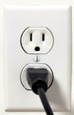
| Unplug/Disconnect the power source to the Call Station | |||
{|style="margin:left;" | |||
|valign="top" | | |||
{|class="wikitable" style="background:white; align:center;" | |||
|- | |||
|[[File:Radio12.png|center|107px]] | |||
< | |} | ||
|} | |||
|} | |||
|} | |||
<br> | |||
---- | |||
<br> | |||
{|style="margin:left; width: 100px; background:#eaf3ff; padding:5px; border:2px solid #000000;" | |||
|- | |||
|<big>'''Step 2.'''</big> | |||
''' | {|style="margin:left; width: 800px; background:#F0F0F0; padding:5px; border:2px solid #000000;" | ||
|valign="top" | | |||
|- | |||
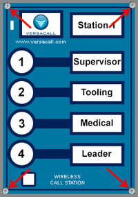
File: | |Loosen the (4) screws on each corner of the Call Station. The screws will spin freely but not detach from the cover when loose. | ||
{|style="margin:left;" | |||
|valign="top" | | |||
{|class="wikitable" style="background:white;" | |||
|- | |||
|[[File:Wire6.png|center|200px]] | |||
< | |} | ||
|} | |||
</ | |} | ||
|} | |||
<br> | |||
---- | |||
<br> | |||
{|style="margin:left; width: 100px; background:#eaf3ff; padding:5px; border:2px solid #000000;" | |||
|- | |||
|<big>'''Step 3.'''</big> | |||
{|style="margin:left; width: 800px; background:#F0F0F0; padding:5px; border:2px solid #000000;" | |||
[[ | |valign="top" | | ||
|- | |||
|Remove the front cover from the case. The circuit board is attached to the front cover. | |||
= | |} | ||
|} | |||
<br> | |||
---- | |||
<br> | |||
{|style="margin:left; width: 100px; background:#eaf3ff; padding:5px; border:2px solid #000000;" | |||
|- | |||
|<big>'''Step 4.'''</big> | |||
{|style="margin:left; width: 800px; background:#F0F0F0; padding:5px; border:2px solid #000000;" | |||
|valign="top" | | |||
|- | |||
|You will need to drill a 7/8 inch hole in the box if the boxes were not sent to VersaCall for drilling. | |||
|} | |||
|} | |||
<br> | |||
---- | |||
<br> | |||
{|style="margin:left; width: 100px; background:#eaf3ff; padding:5px; border:2px solid #000000;" | |||
|- | |||
|<big>'''Step 5.'''</big> | |||
{|style="margin:left; width: 800px; background:#F0F0F0; padding:5px; border:2px solid #000000;" | |||
|valign="top" | | |||
|- | |||
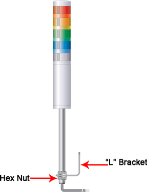
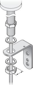
|Remove the hex nut from the light stack pole and insert the end into the 7/8 inch hole that was made. Attach and tighten the hex nut onto the pole. | |||
{|style="margin:left;" | |||
|valign="top" | | |||
{|class="wikitable" style="background:white; align:center;" | |||
|- | |||
|[[File:Wire3.png|center|300px]] || [[File:Wire2.png|center|115px]] | |||
|} | |||
|} | |||
|} | |||
|} | |||
<br> | |||
---- | |||
<br> | |||
{|style="margin:left; width: 100px; background:#eaf3ff; padding:5px; border:2px solid #000000;" | |||
|- | |||
|<big>'''Step 6.'''</big> | |||
{|style="margin:left; width: 800px; background:#F0F0F0; padding:5px; border:2px solid #000000;" | |||
|valign="top" | | |||
|- | |||
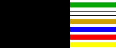
|The wires coming out of the pole and into the box are different colors. Below is a list of colors and what the wire represents to the light stack. | |||
{|style="margin:left;" | |||
|valign="top" | | |||
{|class="wikitable" style="background:white; align:center; width:775px;" | |||
|- | |||
|[[File:Wire4.png|border|center|400px]] | |||
|} | |||
{|class="wikitable" style="background:white; align:center; width:775px;" | |||
|- | |||
|'''Yellow''' - Power wire to the light stack. | |||
|- | |||
|'''Red''' - Connected to the Red light. | |||
|- | |||
|'''Orange''' - Connected to the Amber light. | |||
|- | |||
|'''Blue''' - Connected to the Blue light. | |||
|- | |||
|'''White''' - Connected to the White light. | |||
|- | |||
|'''Green''' - Connected to the Green light. | |||
|} | |||
|} | |||
|} | |||
|} | |||
<br> | |||
---- | |||
<br> | |||
{|style="margin:left; width: 100px; background:#eaf3ff; padding:5px; border:2px solid #000000;" | |||
|- | |||
|<big>'''Step 7.'''</big> | |||
{|style="margin:left; width: 800px; background:#F0F0F0; padding:5px; border:2px solid #000000;" | |||
|valign="top" | | |||
|- | |||
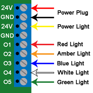
|Each wire will need to be connected to the output bar at the top of the circuit board. To connect the wire, insert it into the hole on the front of the output bar and tighten the screw on top of the bar. Below is a chart on where each wire should be inserted. If your light stack has a different order than the standard (Red, Amber, Blue, White, Green) feel free to arrange the wires on any output you wish except Yellow, it must be connected to 24V. | |||
{|style="margin:left;" | |||
|valign="top" | | |||
{|class="wikitable" style="background:white; align:center; width:775px;" | |||
|- | |||
|[[File:Wire5.png|border|center|300px]] | |||
|} | |||
{|class="wikitable" style="background:white; align:center; width:775px;" | |||
|- | |||
|'''Yellow Wire''' - connect to the '''24V''' output. | |||
|- | |||
|'''Red Wire''' - connect to the '''O1''' output. | |||
|- | |||
|'''Amber Wire''' - connect to the '''O2''' output. | |||
|- | |||
|'''Blue Wire''' - connect to the '''O3''' output. | |||
|- | |||
|'''White Wire''' - connect to the '''O4''' output. | |||
|- | |||
|'''Green Wire''' - connect to the '''O5''' output. | |||
|} | |||
|} | |||
|} | |||
|} | |||
<br> | |||
---- | |||
<br> | |||
{|style="margin:left; width: 100px; background:#eaf3ff; padding:5px; border:2px solid #000000;" | |||
|- | |||
|<big>'''Step 8.'''</big> | |||
{|style="margin:left; width: 800px; background:#F0F0F0; padding:5px; border:2px solid #000000;" | |||
|valign="top" | | |||
|- | |||
|Wrap the excess light stack wire to fit inside the Call Station box. Attach the front plate to the box and hand tighten the (4) screws from Step 2. | |||
{|style="margin:left;" | |||
|valign="top" | | |||
{|class="wikitable" style="background:white; align:center;" | |||
|- | |||
|[[File:Wire6.png|center|200px]] | |||
|} | |||
|} | |||
|} | |||
|} | |||
<br> | |||
---- | |||
<br> | |||
{|style="margin:left; width: 100px; background:#eaf3ff; padding:5px; border:2px solid #000000;" | |||
|- | |||
|<big>'''Step 9.'''</big> | |||
{|style="margin:left; width: 800px; background:#F0F0F0; padding:5px; border:2px solid #000000;" | |||
|valign="top" | | |||
|- | |||
|Plug in power to the Call Station - proceed to Part 2 to configure the lights. | |||
{|style="margin:left;" | |||
|valign="top" | | |||
{|class="wikitable" style="background:white; align:center;" | |||
|- | |||
|[[File:Radio12.png|center|107px]] | |||
|} | |||
|} | |||
|} | |||
|} | |||
<br> | |||
---- | |||
---- | |||
<br> | |||
{|style="margin:auto;" | |||
|+ | |||
[[File:RelatedHowTos.png|center]] | |||
|align="center" | | |||
{| class="wikitable mw-collapsible mw-collapsed" width="400px;" | |||
|- | |||
|style="text-align: center;" | '''Select a Guide Here''' | |||
|- | |||
|[[VT3000 - Install Call Station - Battery|Installation Instructions for a Battery Call Station]] | |||
|- | |||
|[[VT3000 - Install Call Station - Powered|Installation Instructions for a Powered Call Station]] | |||
|- | |||
|[[VT3000 - Add Call Station Configuration|Add a Call Station Configuration]] | |||
|- | |||
|[[VT3000 - Update Configuration - Battery Call Station|Update the Configuration on a Battery Call Station]] | |||
|- | |||
|[[VT3000 - Update Configuration - Powered Call Station|Update the Configuration on a Powered Call Station]] | |||
|- | |||
|[[VT3000 - Update Firmware - Battery Call Station - Wireless|Update the Firmware on a Battery Call Station - Wireless]] | |||
|- | |||
|[[VT3000 - Update Firmware - Powered Call Station - Wireless|Update the Firmware on a Powered Call Station - Wireless]] | |||
|- | |||
|[[VT3000 - Update Firmware - Call Station - Manually|Update the Firmware on a Call Station - Manually]] | |||
|- | |||
|[[VT3000 - Setup Attached Light Stack - Call Station|Configure/Setup Light Stack on the Call Station Configuration]] | |||
|- | |||
|[[VT3000 - Control/Use Attached Light Stack - Call Station|Setup the Use of the Light(s) on the Call Station Configuration]] | |||
|- | |||
|[[VT3000 - Change ISO Code - Call Station - Use Buttons|Change ISO Code on a Call Station using the # 1 - # 4 Buttons]] | |||
|- | |||
|[[VT3000 - Change ISO Code - Call Station - Use Micro SD Card|Change ISO Code on a Call Station using the Micro SD Card]] | |||
|- | |||
|[[VT3000 - Change ISO Code - Call Station - Wirelessly|Change ISO Code on a Call Station using VT3000 Core Software Wirelessly]] | |||
|- | |||
|[[VT3000 - Test Signal Strength - Coverage Test - Powered Call Station|Perform a Coverage Test on a Powered Call Station]] | |||
|- | |||
||[[VT3000 - Test Signal Strength - Coverage Test - Battery Powered Call Station|Perform a Coverage Test on a Battery Powered Call Station]] | |||
|} | |||
|} | |||
<br> | |||
---- | |||
<br> | |||
{|style="margin:auto;" | |||
|+ | |||
[[File:SearchHeader.png|center]] | |||
|align="center" | | |||
{|class="wikitable" | |||
|- | |||
|<inputbox>type=search</inputbox> | |||
|} | |||
|} | |||
<br> | |||
---- | |||
<br> | |||
[[File:VC Footer.png|center]] | |||
{|style="background:transparent; color:black" border="0" height="200" align="center" valign="bottom" cellpadding=10px cellspacing=10px | |||
|+style="background:transparent| | |||
|-align="center" | |||
| | |||
|[[File:LinkedIn.png|Follow Us On LinkedIn|link=https://www.linkedin.com/company/versacall/]] | |||
| | |||
|[[File:BlogIcon.png|View our Blog|link=https://www.versacall.com/blog/]] | |||
|} | |||
<br> | |||
[[Category:VT3000 Core Software]] | |||
[[Category:Device Hardware]] | |||
[[Category:Call Station]] | |||
[[Category:Light Stack]] | |||
Latest revision as of 15:29, 2 January 2024

|

|

|
Overview
|
Requirements
|
Completion Steps
|
Step 1.
|
Step 2.
|
Step 3.
|
Step 4.
|
Step 5.
|
Step 6.
|
Step 7.
|
Step 8.
|
Step 9.
|
|
|

|


