Difference between revisions of "VT3000 - Change ISO Code - Call Station - Use Buttons"
Jump to navigation
Jump to search
SupportAdmin (talk | contribs) |
SupportAdmin (talk | contribs) |
||
| Line 20: | Line 20: | ||
|} | |} | ||
|} | |} | ||
<br> | |||
=Instructions= | =<big>'''Instructions'''</big>= | ||
<br> | |||
'''1.''' Go to the Call Station you want to change the ISO Code on. Ensure it is powered On - Green or Red LED will be blinking in top | {|style="margin:left; width: 100px; background:#eaf3ff; padding:5px; border:2px solid #000000;" | ||
|- | |||
|<big>'''Step 1.'''</big> | |||
File:CSButtonIso1.png | {|style="margin:left; width: 800px; background:#F0F0F0; padding:5px; border:2px solid #000000;" | ||
< | |valign="top" | | ||
|- | |||
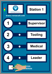
|Go to the Call Station you want to change the ISO Code on. Ensure it is powered On - Green or Red LED will be blinking in top left corner of the device. | |||
'''2.''' Press & Hold down the White Square button - press down the # 3 button. | {|style="margin:left;" | ||
|valign="top" | | |||
{|class="wikitable" style="background:white; align:center;" | |||
File:CSButtonIso2.png | |- | ||
< | |[[File:CSButtonIso1.png|center|281px]] | ||
|} | |||
|} | |||
'''3.''' All of the LED's in the top left corner of the Call Station will turn on - release both buttons when this happens. | |} | ||
|} | |||
<br> | |||
File:CSButtonIso3.png | ---- | ||
< | <br> | ||
{|style="margin:left; width: 100px; background:#eaf3ff; padding:5px; border:2px solid #000000;" | |||
|- | |||
'''4.''' You will need to understand what buttons represent what numbers before proceeding - this is explained below: | |<big>'''Step 2.'''</big> | ||
{|style="margin:left; width: 800px; background:#F0F0F0; padding:5px; border:2px solid #000000;" | |||
|valign="top" | | |||
|- | |||
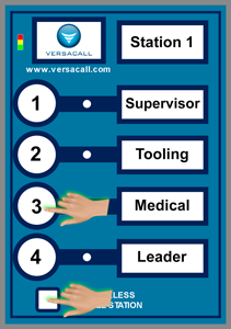
|Press & Hold down the White Square button - press down the # 3 button. | |||
{|style="margin:left;" | |||
'''5.''' Press & Release the # 4 button. | |valign="top" | | ||
{|class="wikitable" style="background:white; align:center;" | |||
|- | |||
File:CSButtonIso4.png | |[[File:CSButtonIso2.png|center|211px]] | ||
< | |} | ||
|} | |||
|} | |||
'''6.''' The Red LED light next to either the # 1 or # | |} | ||
<br> | |||
---- | |||
File:CSButtonIso5.png | <br> | ||
< | {|style="margin:left; width: 100px; background:#eaf3ff; padding:5px; border:2px solid #000000;" | ||
|- | |||
|<big>'''Step 3.'''</big> | |||
'''7.''' Using the button representation in step # 4, you can determine what ISO Code the Call Station is set to. | {|style="margin:left; width: 800px; background:#F0F0F0; padding:5px; border:2px solid #000000;" | ||
|valign="top" | | |||
|- | |||
|All of the LED's in the top left corner of the Call Station will turn on - release both buttons when this happens. | |||
{|style="margin:left;" | |||
|valign="top" | | |||
'''8.''' Using the # 1 and # | {|class="wikitable" style="background:white; align:center;" | ||
|- | |||
|[[File:CSButtonIso3.png|center|273px]] | |||
File:CSButtonIso6.png | |} | ||
< | |} | ||
|} | |||
|} | |||
'''9.''' Once you have it programmed in, press and release the # 4 button. The Red LED light next to the buttons will blink the ISO Code that you entered. | <br> | ||
---- | |||
<br> | |||
File:CSButtonIso4.png | {|style="margin:left; width: 100px; background:#eaf3ff; padding:5px; border:2px solid #000000;" | ||
File:CSButtonIso5.png | |- | ||
< | |<big>'''Step 4.'''</big> | ||
{|style="margin:left; width: 800px; background:#F0F0F0; padding:5px; border:2px solid #000000;" | |||
'''10.''' | |valign="top" | | ||
|- | |||
|You will need to understand what buttons represent what numbers before proceeding - this is explained below: | |||
File:CSButton6.png | {|style="margin:left;" | ||
< | |valign="top" | | ||
{|class="wikitable" style="background:white; align:center;" | |||
|- | |||
'''11.''' Open the VT3000 web interface - log in | |'''Button 1''' - represents a value of 1. | ||
|- | |||
|'''Button 2''' - represents a value of 10. | |||
File: | |- | ||
File: | |'''Button 3''' - represents a value of 100. | ||
< | |} | ||
|} | |||
|} | |||
'''12.''' | |} | ||
<br> | |||
---- | |||
File:CS3.gif | <br> | ||
< | {|style="margin:left; width: 100px; background:#eaf3ff; padding:5px; border:2px solid #000000;" | ||
|- | |||
|<big>'''Step 5.'''</big> | |||
{|style="margin:left; width: 800px; background:#F0F0F0; padding:5px; border:2px solid #000000;" | |||
|valign="top" | | |||
|- | |||
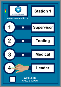
|Press & Release the # 4 button. | |||
{|style="margin:left;" | |||
|valign="top" | | |||
{|class="wikitable" style="background:white; align:center;" | |||
|- | |||
|[[File:CSButtonIso4.png|center|211px]] | |||
|} | |||
|} | |||
|} | |||
|} | |||
<br> | |||
---- | |||
<br> | |||
{|style="margin:left; width: 100px; background:#eaf3ff; padding:5px; border:2px solid #000000;" | |||
|- | |||
|<big>'''Step 6.'''</big> | |||
{|style="margin:left; width: 800px; background:#F0F0F0; padding:5px; border:2px solid #000000;" | |||
|valign="top" | | |||
|- | |||
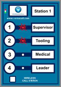
|The Red LED light next to either the #1, #2 or #3 buttons will blink. | |||
{|style="margin:left;" | |||
|valign="top" | | |||
{|class="wikitable" style="background:white; align:center;" | |||
|- | |||
|[[File:CSButtonIso5.png|center|211px]] | |||
|} | |||
|} | |||
|} | |||
|} | |||
<br> | |||
---- | |||
<br> | |||
{|style="margin:left; width: 100px; background:#eaf3ff; padding:5px; border:2px solid #000000;" | |||
|- | |||
|<big>'''Step 7.'''</big> | |||
{|style="margin:left; width: 800px; background:#F0F0F0; padding:5px; border:2px solid #000000;" | |||
|valign="top" | | |||
|- | |||
|Using the button representation in step # 4, you can determine what ISO Code the Call Station is set to. | |||
{|style="margin:left;" | |||
|valign="top" | | |||
{|class="wikitable" style="background:white; align:center;" | |||
|- | |||
|'''Example 1''' - if the #1 button LED blinks 3 times, this would mean that the Call Station is programmed to Isolation Code 3. | |||
|- | |||
|'''Example 2''' - if the #1 button LED blinks 1 time & the #2 button LED blinks 1 time, this would mean that the Call Station is programmed to Isolation Code 11. | |||
|} | |||
|} | |||
|} | |||
|} | |||
<br> | |||
---- | |||
<br> | |||
{|style="margin:left; width: 100px; background:#eaf3ff; padding:5px; border:2px solid #000000;" | |||
|- | |||
|<big>'''Step 8.'''</big> | |||
{|style="margin:left; width: 800px; background:#F0F0F0; padding:5px; border:2px solid #000000;" | |||
|valign="top" | | |||
|- | |||
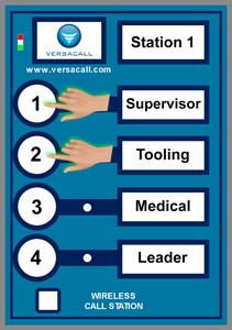
|Using the #1, #2 and #3 buttons, press and release the proper sequence to get the ISO Code that you want to assign this Call Station. | |||
{|style="margin:left;" | |||
|valign="top" | | |||
{|class="wikitable" style="background:white; align:center;" | |||
|- | |||
|[[File:CSButtonIso6.png|center|211px]] | |||
|} | |||
|} | |||
|} | |||
|} | |||
<br> | |||
---- | |||
<br> | |||
{|style="margin:left; width: 100px; background:#eaf3ff; padding:5px; border:2px solid #000000;" | |||
|- | |||
|<big>'''Step 9.'''</big> | |||
{|style="margin:left; width: 800px; background:#F0F0F0; padding:5px; border:2px solid #000000;" | |||
|valign="top" | | |||
|- | |||
|Once you have it programmed in, press and release the # 4 button. The Red LED light next to the buttons will blink the ISO Code that you entered. | |||
{|style="margin:left;" | |||
|valign="top" | | |||
{|class="wikitable" style="background:white; align:center;" | |||
|- | |||
|[[File:CSButtonIso4.png|center|211px]] || [[File:CSButtonIso5.png|center|211px]] | |||
|} | |||
|} | |||
|} | |||
|} | |||
<br> | |||
---- | |||
<br> | |||
{|style="margin:left; width: 100px; background:#eaf3ff; padding:5px; border:2px solid #000000;" | |||
|- | |||
|<big>'''Step 10.'''</big> | |||
{|style="margin:left; width: 800px; background:#F0F0F0; padding:5px; border:2px solid #000000;" | |||
|valign="top" | | |||
|- | |||
|If the LED's showed the correct ISO code - press the square button at the bottom of the Call Station. This will save the ISO Code and take the device out of program mode. If the ISO Code is incorrect, repeat steps 7 to 9. | |||
{|style="margin:left;" | |||
|valign="top" | | |||
{|class="wikitable" style="background:white; align:center;" | |||
|- | |||
|[[File:CSButton6.png|center|211px]] | |||
|} | |||
|} | |||
|} | |||
|} | |||
<br> | |||
---- | |||
<br> | |||
{|style="margin:left; width: 100px; background:#eaf3ff; padding:5px; border:2px solid #000000;" | |||
|- | |||
|<big>'''Step 11.'''</big> | |||
{|style="margin:left; width: 800px; background:#F0F0F0; padding:5px; border:2px solid #000000;" | |||
|valign="top" | | |||
|- | |||
|Open the VT3000 web interface – select VT3000 Core Software - log in – select Diagnostics – select Devices. | |||
{|style="margin:left;" | |||
|valign="top" | | |||
{|class="wikitable" style="background:white; align:center;" | |||
|- | |||
|[[File:3215 2.png|center|101px]] || [[File:3215 3.png|center|101px]] | |||
|- | |||
|style="text-align:center" | '''Diagnostics''' ||style="text-align:center" | '''Device Status''' | |||
|} | |||
|} | |||
|} | |||
|} | |||
<br> | |||
---- | |||
<br> | |||
{|style="margin:left; width: 100px; background:#eaf3ff; padding:5px; border:2px solid #000000;" | |||
|- | |||
|<big>'''Step 12.'''</big> | |||
{|style="margin:left; width: 800px; background:#F0F0F0; padding:5px; border:2px solid #000000;" | |||
|valign="top" | | |||
|- | |||
|Find the device that you switched the ISO Code on - under the Network Name, ensure it is showing the correct name of the Coordinator. | |||
{|style="margin:left;" | |||
|valign="top" | | |||
{|class="wikitable" style="background:white; align:center;" | |||
|- | |||
|[[File:CS3.gif|center|703px]] | |||
|} | |||
|} | |||
|} | |||
|} | |||
<br> | |||
---- | ---- | ||
---- | ---- | ||
<br> | |||
{|style="margin: auto; background:#eaf3ff; border:1px solid #2a4b8d" | {|style="margin: auto; background:#eaf3ff; border:1px solid #2a4b8d" | ||
|valign="top" | | |valign="top" | | ||
| Line 163: | Line 315: | ||
</inputbox> | </inputbox> | ||
|} | |} | ||
<br> | |||
[[Category:VT3000 Core Software]] | [[Category:VT3000 Core Software]] | ||
[[Category:Diagnostics]] | [[Category:Diagnostics]] | ||
[[Category:Device Status]] | [[Category:Device Status]] | ||
[[Category:Call Station]] | [[Category:Call Station]] | ||
Revision as of 22:39, 22 November 2021
|
|
Instructions
Step 1.
|
Step 2.
|
Step 3.
|
Step 4.
|
Step 5.
|
Step 6.
|
Step 7.
|
Step 8.
|
Step 9.
|
Step 10.
|
Step 11.
|
Step 12.
|

